Touch display system with optical touch detector

a display system and detector technology, applied in the field of touch display systems, can solve the problems of reducing the light transmittance of the touch screen and impairing the performance of the touch display system

Inactive Publication Date: 2010-10-28
HON HAI PRECISION IND CO LTD
View PDF13 Cites 13 Cited by
  • Summary
  • Abstract
  • Description
  • Claims
  • Application Information

AI Technical Summary

Problems solved by technology

However, the resistance film and the capacitance film reduce the light transmittance of the touch screen.
Furthermore, the...

Method used


Image

  • Touch display system with optical touch detector
  • Touch display system with optical touch detector
  • Touch display system with optical touch detector

Examples


first embodiment

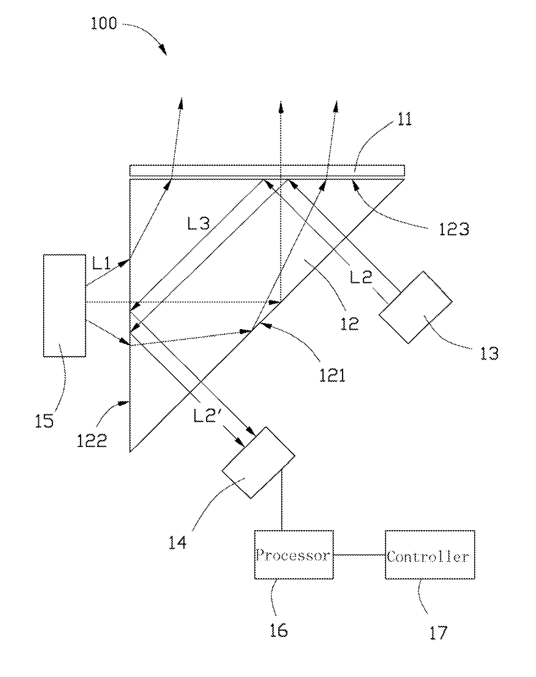
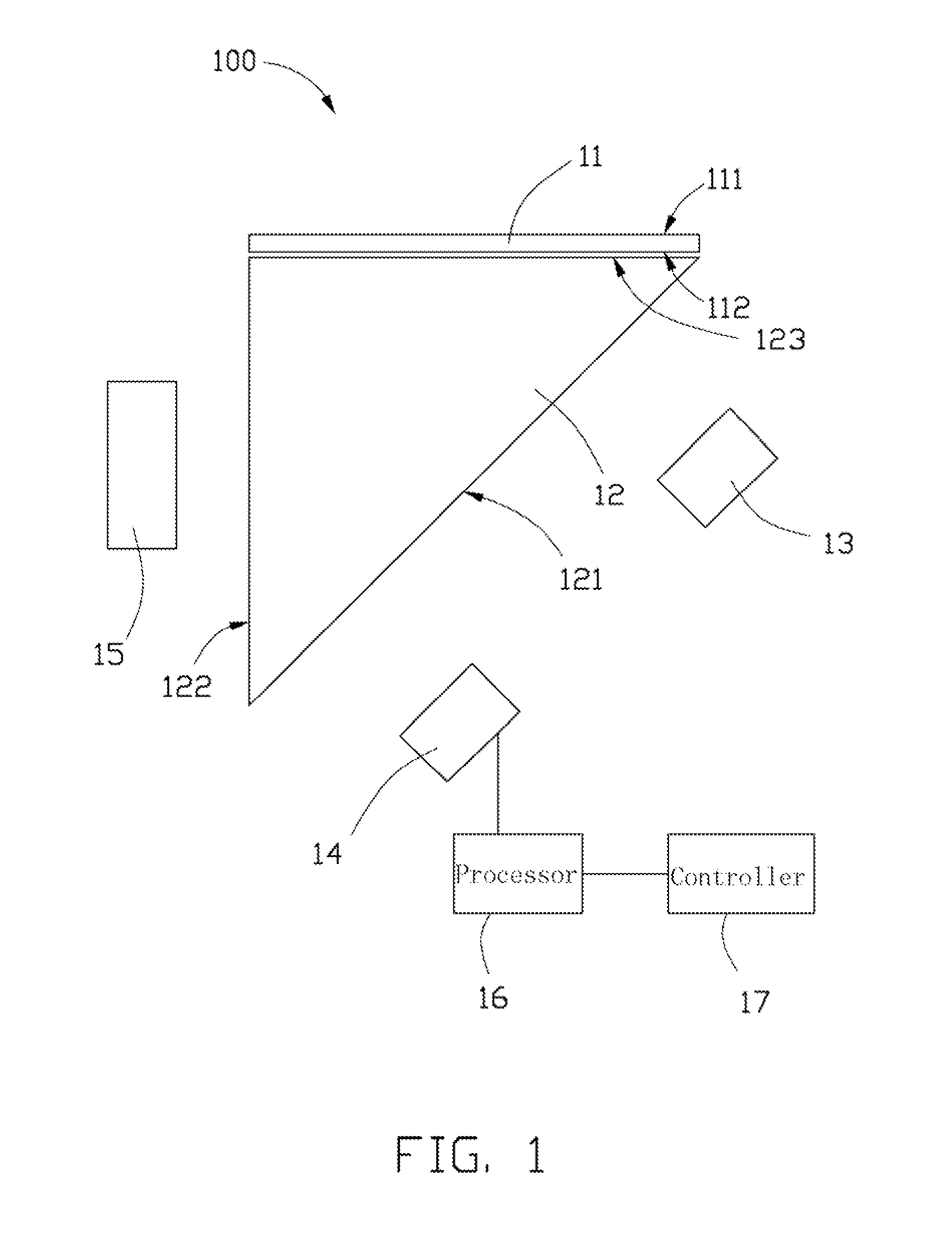
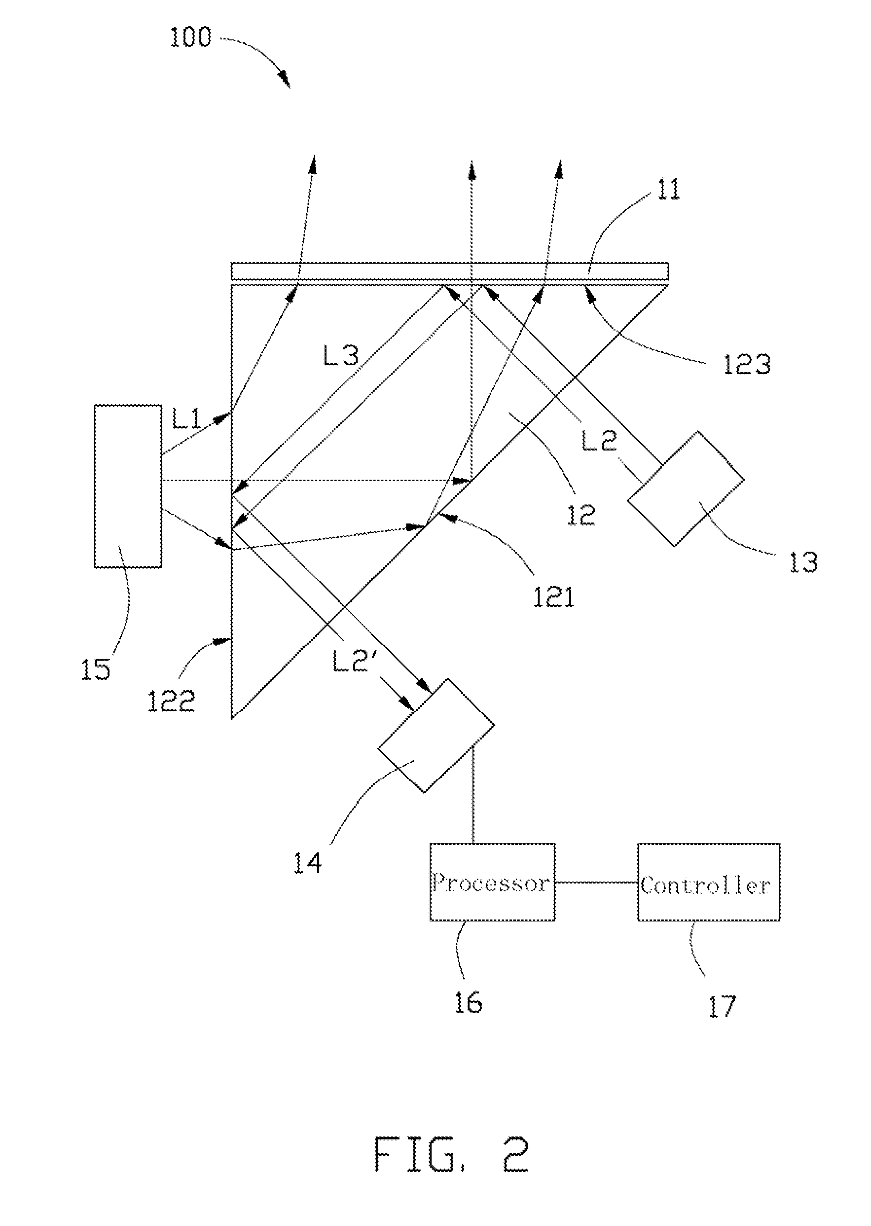
[0013]Referring to FIG. 1, a touch display system 100 in accordance with a first embodiment is shown. The touch display system 100 includes a touch screen 11, a prism 12, an infrared light source 13, an infrared image sensor 14, a visible light source 15, a processor 16, and a controller 17.

[0014]The touch screen 11 includes a touch display surface 111 facing a user, and an opposite back surface 112. The touch screen 11 is in the form of a sheet, and thus is flexible. The wording “flexible” herein and after presents the same or similar characteristic as follows: when a touch is applied to the touch screen 11 at a touch position, e.g., by a stylus 18 (see FIG. 3), the touch screen 11 is bent at the touch position; and after the stylus 18 is removed, the bent portion of the touch screen 11 rebounds to its original shape.

[0015]The prism 12 is substantially an isosceles right-angled triangular prism, and includes a first side surface 123, a second side surface 122 and a hypotenuse surfa...

second embodiment

[0022]Referring to FIG. 4, a touch display system 200 in accordance with a second embodiment is shown. The touch display system 200 is essentially similar in structure, principle, and operation to the touch display system 100 described above. However, the touch display system 200 includes a plurality of prisms 22 juxtaposed one by another, with first side surfaces thereof connected to each other. The first side surfaces face a touch screen 21. An infrared light source 23, an infrared image sensor 24 and a visible light source 25 are arranged around two sides of each prism 22. A processor 26 is electrically connected to each of the infrared image sensors 24, and a controller 27 is electrically connected to the processor 26.


PUM


Abstract

An exemplary touch display system includes a flexible touch screen, a prism, an infrared light source, an infrared image sensor, and a processor. The prism is substantially isosceles right-angled triangular shaped, with a first side surface thereof being disposed adjacent to but spaced apart from back surface of the touch screen by air, wherein when a touch is applied to the touch display surface at a touch position, the touch screen is bent at the touch position and contact the prism at a contact position corresponding to the touch position. The infrared light source and the infrared image sensor are arranged adjacent to and facing to a hypotenuse surface of the prism. The processor is configured for processing image signals from the image sensor and obtaining the contact position based on light intensities of the image signals, thereby obtaining the touch position on the touch display surface.

Description

BACKGROUND[0001]1. Technical Field[0002]The present disclosure relates to touch display systems, and particularly, to a touch display system with an optical touch detector for detecting touch positions.[0003]2. Description of Related Art[0004]Touch display systems have been widely used in electronic devices, such as personal digital assistants (PDAs) and mobile phones.[0005]Touch screens and touch detectors are key components for touch display systems. The touch screen is a display which can display images according to touches applied thereto. The touch detector is for detecting touch positions of a user's finger or a stylus on the touch screen. Currently, resistance films, capacitance films and surface acoustic wave systems are popularly used as touch detectors. However, the resistance film and the capacitance film reduce the light transmittance of the touch screen. Furthermore, the surface acoustic wave system is liable to absorb dust and water, thereby impairing the performance o...

Claims


Application Information

Patent Timeline
IPC IPC(8): G06F3/042
CPCG06F3/0428
Inventor YUAN, KUN-I
Owner HON HAI PRECISION IND CO LTD
Why Eureka
Try Eureka