Reversible electrodeposition optical modulation device with conducting polymer counter electrode

a counter electrode and optical modulation device technology, applied in non-linear optics, instruments, optics, etc., can solve the problems of reducing device lifetime, limiting switching speed and cycle life, and generating heat, so as to achieve minimal effect of counter electrode on device performan

Inactive Publication Date: 2005-11-10
TELEDYNE LICENSING
View PDF9 Cites 37 Cited by
  • Summary
  • Abstract
  • Description
  • Claims
  • Application Information

AI Technical Summary

Benefits of technology

[0019] The conducting polymer counter electrode of the present invention may also be advantageous for reversible electrodeposition devices designed to operate at radio frequencies. In this case, the effects of the counter electrode on device performance would be minimal since ...

Problems solved by technology

However, the electrochromic smart window devices which are known in the prior art have narrow dynamic ranges and involve light absorption during operation, resulting in heat being generated and transferred into the interior space by conduction, convection and infrared radiation.
In addition, electrochromic devices typically utilize a relatively slow ion insertion electrochemical process that limits switching speed and cycle life.
Heating of electrochromic devices by light absorption further reduces the device lifetime.
Other types of smart windows, such as liquid crystal and suspended particle devices, also have limited dynamic range and typically have the added disadvantage of requiring a continuously applied voltage to maintain a given transmissive state.
Commercialization of REM smart window devices has been hindered by the expense and performance of the locally distributed counter electrode, which must present a relatively small cross-sectional area to avoid excessive light blockage that would decrease the maximum transmission of the device.
The photolithographic process is inherently expensive and not readily scalable to large areas.
In addition, fine grid lines (<10 μm wide) are needed so as to be invisible to the eye, but grid lines of such size are prone to damage during the photoresist liftoff process, which further increases the fabrication costs.
Fine grid lines also tend to produce light interference patterns that distort images seen through the window.
Counter electrodes involving reversible mirror metal electrdeposition have significant disadvantages for REM devices, depending on the type of device.
One disadvantage for transmissive devices is that a compromise is required, even for dot matrix electrodes, between...

Method used


Image

  • Reversible electrodeposition optical modulation device with conducting polymer counter electrode
  • Reversible electrodeposition optical modulation device with conducting polymer counter electrode
  • Reversible electrodeposition optical modulation device with conducting polymer counter electrode

Examples


Embodiment Construction

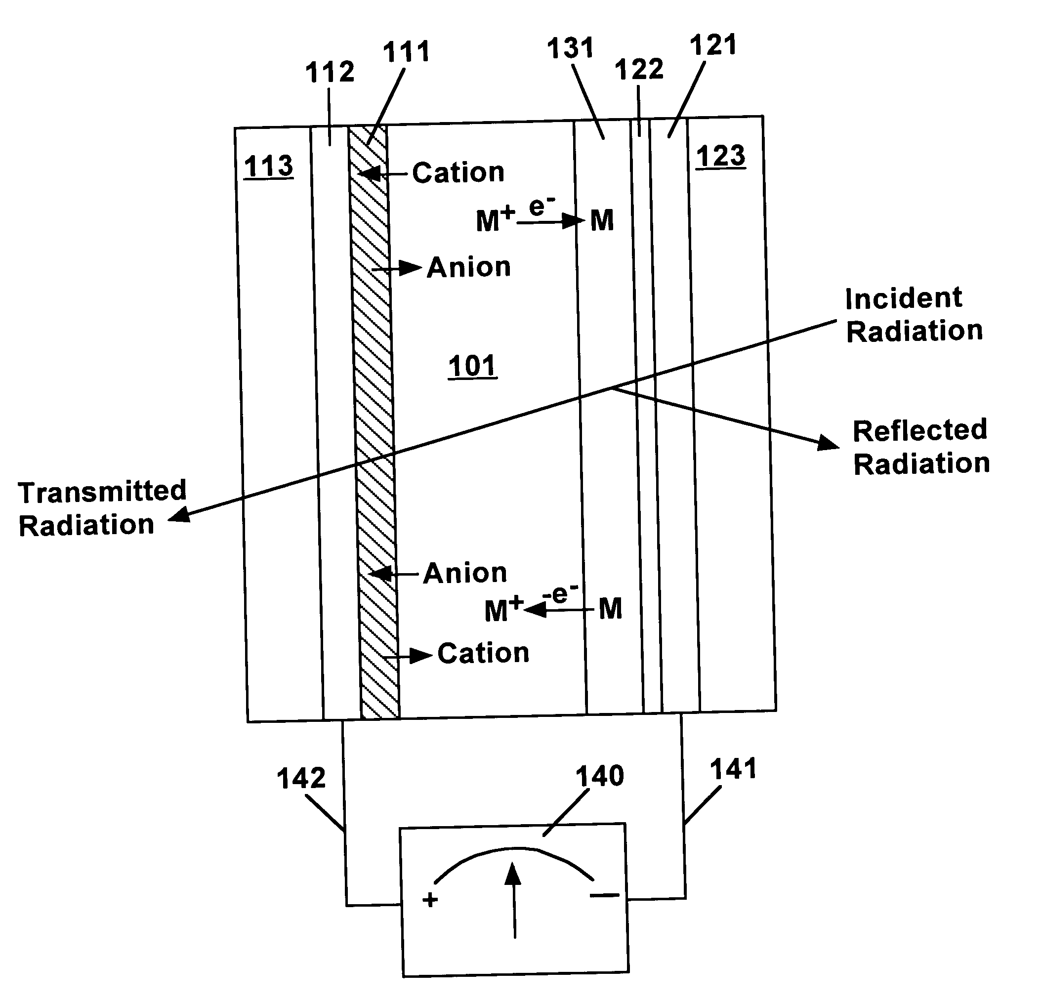
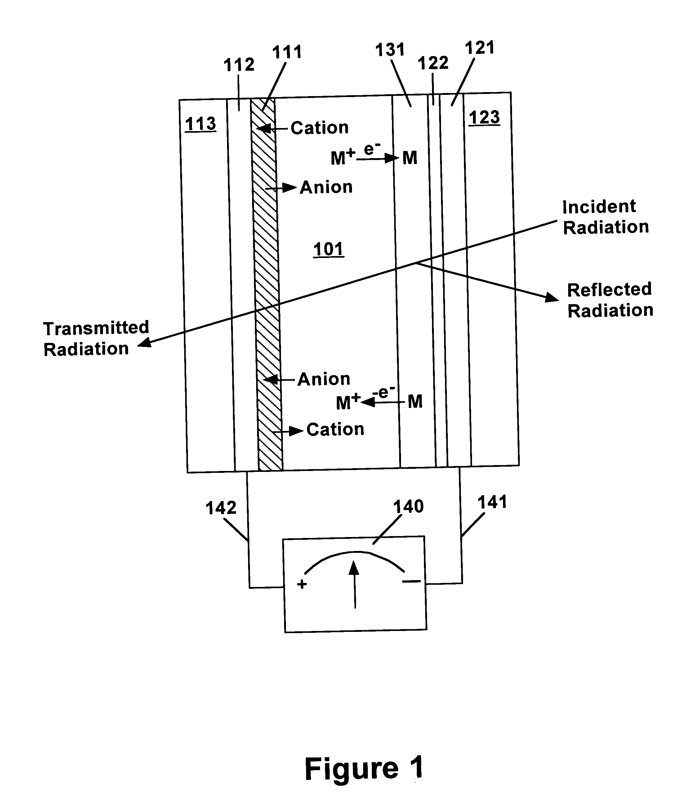
[0024] This invention provides an optical modulation device for controlling the propagation of electromagnetic radiation comprising a conducting polymer counter electrode, an electrolyte containing ions of an electrodepositable metal, and an optical modulation electrode at which reversible metal electrodeposition occurs. As used in this document, the term “optical” encompasses radiation throughout the electromagnetic spectrum, including visible light, infrared radiation, and radio frequency radiation. The optical modulation device of the present invention may be designed to control the propagation of electromagnetic radiation in any wavelength region. The term “transparent” denotes substantially high transmission of the electromagnetic radiation whose propagation is controlled by the optical modulation device. The term “conducting polymer” also encompasses the term “electroactive conjugated polymer”, which is also used in the literature.

[0025] Optical modulation devices according t...


PUM


Abstract

An optical modulation device includes an electrolyte containing electrodepositable metal ions sandwiched between a conducting polymer counter electrode and an optical modulation electrode involving reversible metal electrodeposition. The conducting polymer counter electrode does not generate mobile reactive species, and avoids the light blocking associated with grid or dot matrix electrodes involving reversible metal electrodeposition. A polyaniline counter electrode in a smart window device employing a reversible electrochemical mirror modulation electrode provides high light transmission, fast switching, and coloration to mask the backside of the mirror electrode.

Description

CROSS-REFERENCE TO RELATED APPLICATIONS [0001] This application is related to U.S. Pat. Nos. 5,903,382, 5,923,456, 6,111,685, 6,166,847, 6,256,135, 6,301,039, 6,400,491 and 6,552,843, and to U.S. patent application, Ser. No. 10 / 211,494, filed Aug. 1, 2002 (entitled “Locally-Distributed Electrode and Method of Fabrication”), Ser. No. 10 / 256,841, filed Sep. 27, 2002, (entitled “Optimum Switching of a Reversible Electrochemical Mirror Device), and Ser. No. 10 / 355,760, filed 31 Jan. 2003 (entitled “Locally-Switched Reversible Electrodeposition Optical Modulator”), all of which are assigned to the assignee of the present application. The teaching of each of these patents and patent applications is incorporated herein by reference.U.S. GOVERNMENT RIGHTS [0002] This invention was made with Government support under Contract No. DE-FC26-03NT-41951 awarded by the Department of Energy. The Government has certain rights in this invention.BACKGROUND OF THE INVENTION [0003] 1. Field of the Invent...

Claims


Application Information

Patent Timeline
IPC IPC(8): G02F1/155G02F1/1506
CPCG02F2001/1555G02F1/1506
Inventor WARREN, LESLIE F. JR.TENCH, D. MORGAN
Owner TELEDYNE LICENSING
Why Eureka
Try Eureka