Optical sensors and algorithms for controlling automatic bathroom flushers and faucets
What is Al technical title?
Al technical title is built by PatSnap Al team. It summarizes the technical point description of the patent document.
an automatic bathroom and automatic flushing technology, applied in the direction of diaphragm valves, engine diaphragms, operating means/releasing devices of valves, etc., can solve the problems of limiting the range of the emitter and/or receiver, the object can still provide a false trigger to the faucet, and the problem of affecting the operation of the devi
Inactive Publication Date: 2010-11-04
GULER FATIH +5
View PDF105 Cites 14 Cited by
Summary
Abstract
Description
Claims
Application Information
AI Technical Summary
This helps you quickly interpret patents by identifying the three key elements:
Problems solved by technology
Method used
Benefits of technology
Problems solved by technology
However, a coat or another object can still provide a false trigger to the faucet.
In the optical sensor, the emitter power and / or the receiver sensitivity is limited to restrict the sensor's range to eliminate reflections from the sink, or from the bathroom walls or other installed objects.
Frequently, problems arise due to highly reflective doors and walls, mirrors, highly reflective sinks, the shape of different sinks, water in the sink, the colors and rough / shiny surfaces of fabrics, and moving users who are walking by but not using the facility.
Mirrors, doors, walls, and sinks are not valid targets, although they may reflect more energy back to the receiver than rough surfaces at the right angle incidence.
Depending on the design, the emitter (or the receiver) may consume a large amount of power and thus deplete the battery over time (or require large batteries).
The cost of battery replacement involves not only the cost of batteries, but more importantly the labor cost, which may be relatively high for skilled personnel.
Method used
Image
Click on the blue label to locate the original text in one second.
Reading with bidirectional positioning of images and text.
Examples
Embodiment Construction
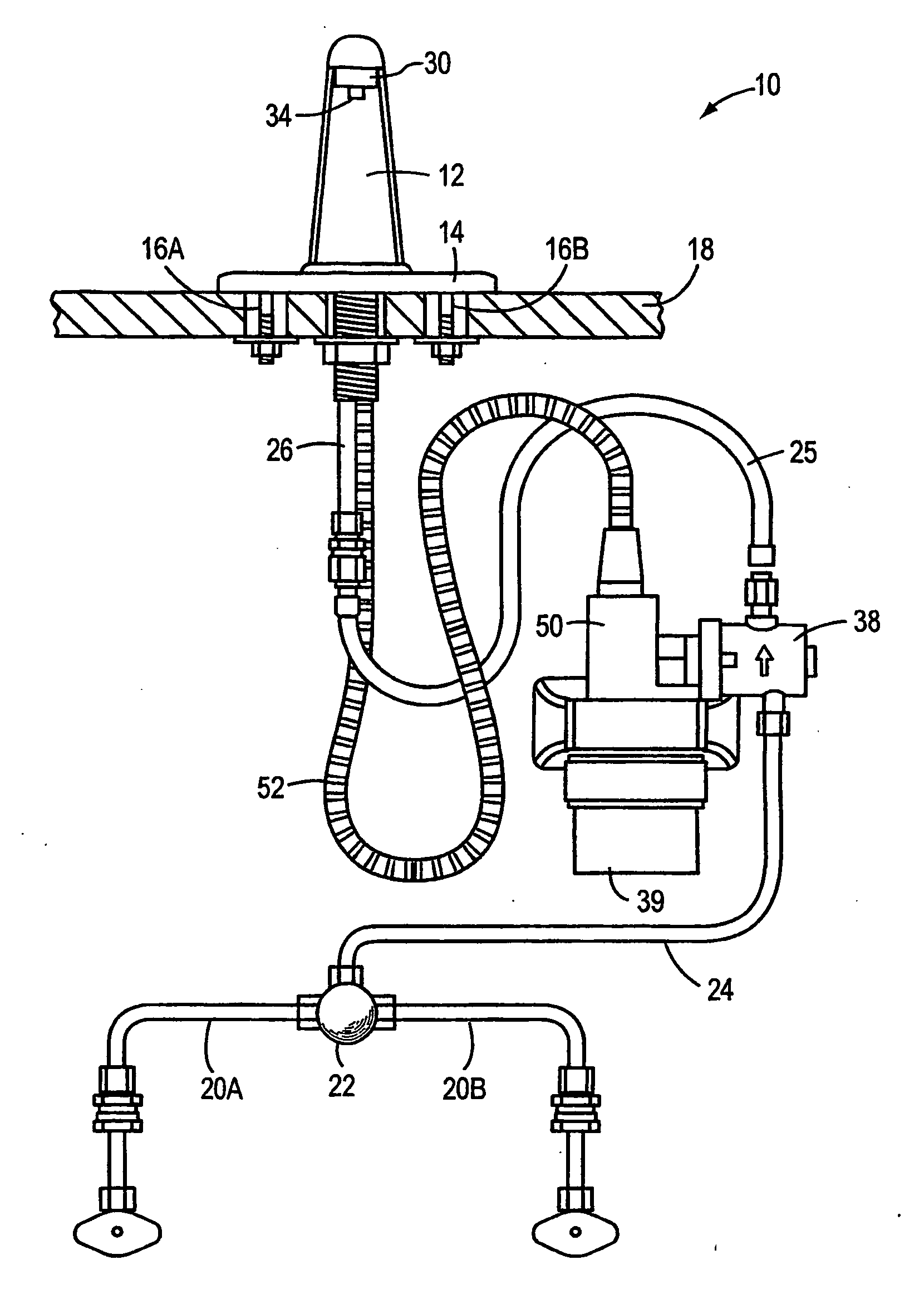
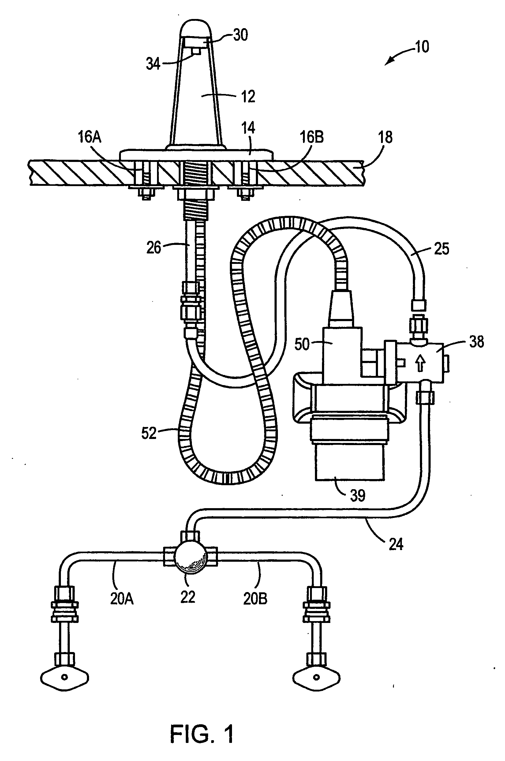
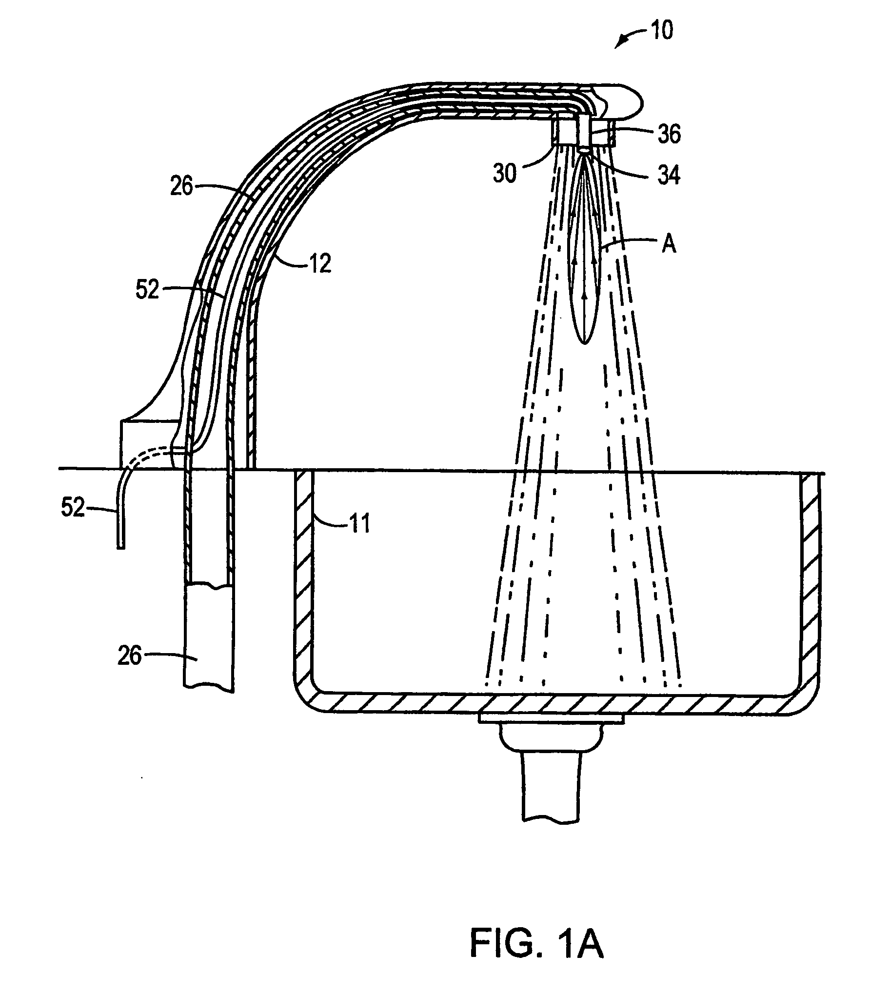
[0053]FIG. 1 shows an automatic faucet system 10 controlled by a sensor providing signals to a control circuit constructed and arranged to control operation of an automatic valve. The automatic valve, in turn, controls the flow of hot and cold water before or after mixing.
[0054]Automatic faucet system 10 includes a faucet body 12 and an aerator 30, including a sensor port 34. Automatic faucet system 10 also includes a faucet base 14 and screws 16A and 16B for attaching the faucet to a deck 18. A cold water pipe 20A and a hot water pipe 20B are connected to a mixing valve 22 providing a mixing ratio of hot and cold water (which ratio can be changed depending on the desired water temperature). Water conduit 24 connects mixing valve 22 to a solenoid valve 38. A flow control valve 38 controls water flow between water conduit 24 and a water conduit 25. Water conduit 25 connects valve 38 to a water conduit 26 partially located inside faucet body 12, as shown. Water conduit 26 delivers wat...
PUM
Abstract
The present invention is directed to novel optical sensors and novel methods for sensing optical radiation that can be used to control the operation of automatic faucets and flushers. The novel sensors and flow controllers require only small amounts of electrical power for sensing users of bathroom facilities, enabling battery operation for many years. An electronic system for controlling fluid flow may include an electromagnetic actuator, a controller and an optical sensor. Preferred embodiments include a control circuit constructed to sample periodically the detector based on the amount of light detected; a control circuit constructed to adjust a sample period based on the detected amount of light after determining whether a facility is in use; a detector optically coupled to the input port using an optical fiber; the input port may be located in an aerator of the electronic faucet; the system includes batteries for powering the electronic faucet. These embodiments may also include a variety of other features. A passive optical sensor includes a light detector sensitive to ambient (room) light for controlling the operation of automatic faucets or automatic bathroom flushers. An active optical sensor includes a light emitter and a light detector. The detected signals may be processed using novel algorithms
Description
[0001]This application is a continuation of U.S. application Ser. No. 11 / 159,422 filed on Jun. 22, 2005, which is a continuation of PCT Application PCT / US03 / 041303, filed on Dec. 26, 2003, which is a continuation-in-part of PCT Application PCT / US03 / 38730, entitled “Passive Sensors for Automatic Faucets and Bathroom Flushers” filed on Dec. 4, 2003, which claims priority from U.S. Application 60 / 513,722, “Automatic Faucets with Novel Flow Control Sensors,” filed on Oct. 22, 2003 and is a continuation-in-part of PCT Application PCT / US03 / 20117, “Irrigation Systems and Control Methods,” filed on Jun. 24, 2003; and PCT Application PCT / US02 / 41576, “Automatic Bathroom Flushers” filed on Dec. 26, 2002; all of which are incorporated by reference.[0002]The PCT / US03 / 041303 application is also a continuation-in-part of PCT Application PCT / US02 / 38757, “Electronic Faucets for Long Term Operation,” filed on Dec. 4, 2002; and PCT Application PCT / US02 / 38758, “Automatic Bathroom Flushers,” filed on De...
Claims
Application Information
Patent Timeline
Application Date:The date an application was filed.
Publication Date:The date a patent or application was officially published.
First Publication Date:The earliest publication date of a patent with the same application number.
Issue Date:Publication date of the patent grant document.
PCT Entry Date:The Entry date of PCT National Phase.
Estimated Expiry Date:The statutory expiry date of a patent right according to the Patent Law, and it is the longest term of protection that the patent right can achieve without the termination of the patent right due to other reasons(Term extension factor has been taken into account ).
Invalid Date:Actual expiry date is based on effective date or publication date of legal transaction data of invalid patent.
Patent Type & Authority Applications(United States)