Method for determining the profile depth of a tire and/or a tire characteristic, and a tire

a tire and profile technology, applied in the field of tire profile depth and tire characteristic, to achieve the effect of convenient and cost-effective measurement of the magnetic field and accurate and reliable measuremen

Active Publication Date: 2010-11-04
CONTINENTAL TEVES AG & CO OHG
View PDF4 Cites 49 Cited by
  • Summary
  • Abstract
  • Description
  • Claims
  • Application Information

AI Technical Summary

Benefits of technology

[0030]One advantage of the invention is that both the indicator element, which indicates the wear of the tire or the tire characteristic, and the magnetic field sensor are arranged in or on the tire. As a result, the distance between the indicator element and the magnetic field sensor is predefined and is independent of, for example, the spring compression of the wheel. Furthermore, the distance between the indicator element and the magnetic field sensor is smaller than if the magnetic field sensor is arranged outside the tire, for example in the wheel case. Both of these facts facilitate accurate and reliable measurement of the magnetic field.
[0031]A further advantage of the invention is that the magnetic field sensor can be integrated into an electronic module of a directly measuring tire pressure-monitoring system. Such electronic modules are mounted, for example, in the region of the tread on the inner liner of the tire and comprise, for example, at least one or more of the following elements: a pressure sensor, a temperature sensor, a battery and / or a generator for generating electrical energy from kinetic energy, an electronic circuit for evaluating signals, and components for transmitting and / or receiving signals. It is therefore easily and cost-effectively possible also to integrate a magnetic field sensor into such a module.

Problems solved by technology

Since the measuring element and sensor circuit are cast into the tire it is not possible, for example in the case of a malfunction of the sensor, to replace the faulty components of the wear sensor.

Method used


Image

  • Method for determining the profile depth of a tire and/or a tire characteristic, and a tire
  • Method for determining the profile depth of a tire and/or a tire characteristic, and a tire
  • Method for determining the profile depth of a tire and/or a tire characteristic, and a tire

Examples


fourth exemplary embodiment

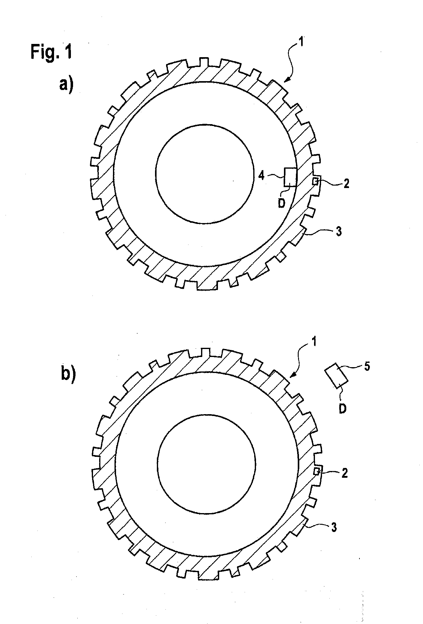
[0050]The invention permits detection of wear of a tire profile at a defined wear point and can be easily and cost-effectively combined with tire pressure sensors etc. (tire modules 4) mounted in the interior of the tire (see first, third and fourth exemplary embodiment), since the magnetic field sensor D is also arranged in the interior of the tire.

[0051]In addition to or as an alternative to the detection of the residual profile of the tire, the invention permits at least one tire characteristic, which is encoded in the tire by means of the indicator element or the indicator elements 2, 11, to be determined.

fifth exemplary embodiment

[0052]Correspondingly, according to a further exemplary embodiment of the invention, it is possible to differentiate between summer tires and winter tires. In addition to the differentiation of summer tires and winter tires, any other tire properties can be correspondingly encoded as a black / white decision. For example, the differentiation of summer tires and winter tires can be achieved by means of the polarity of the magnetic fields of the permanent magnet or magnets 2, 12 inserted, in particular, into the tire (in, for example, the first, second or fourth exemplary embodiments). The detection of the summer tires or winter tires is realized, for example, by means of the installation direction, for example the north pole of the magnet 2, 12 points radially outward from the tire in the case of summer tires, while in the case of winter tires the south pole of the magnet 2, 12 points radially outward. This method of tire detection is particularly advantageous in a passenger car which ...

third exemplary embodiment

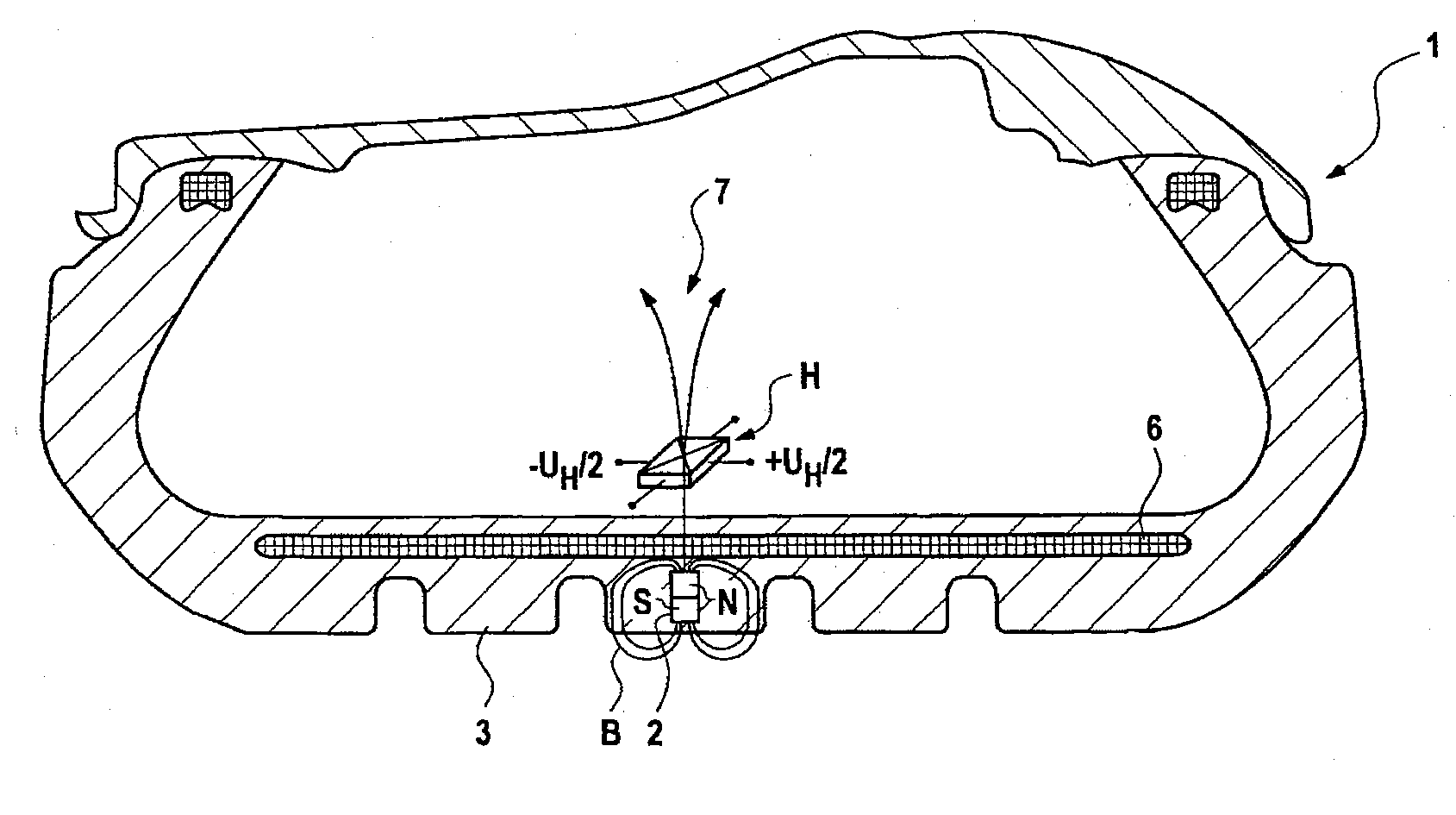
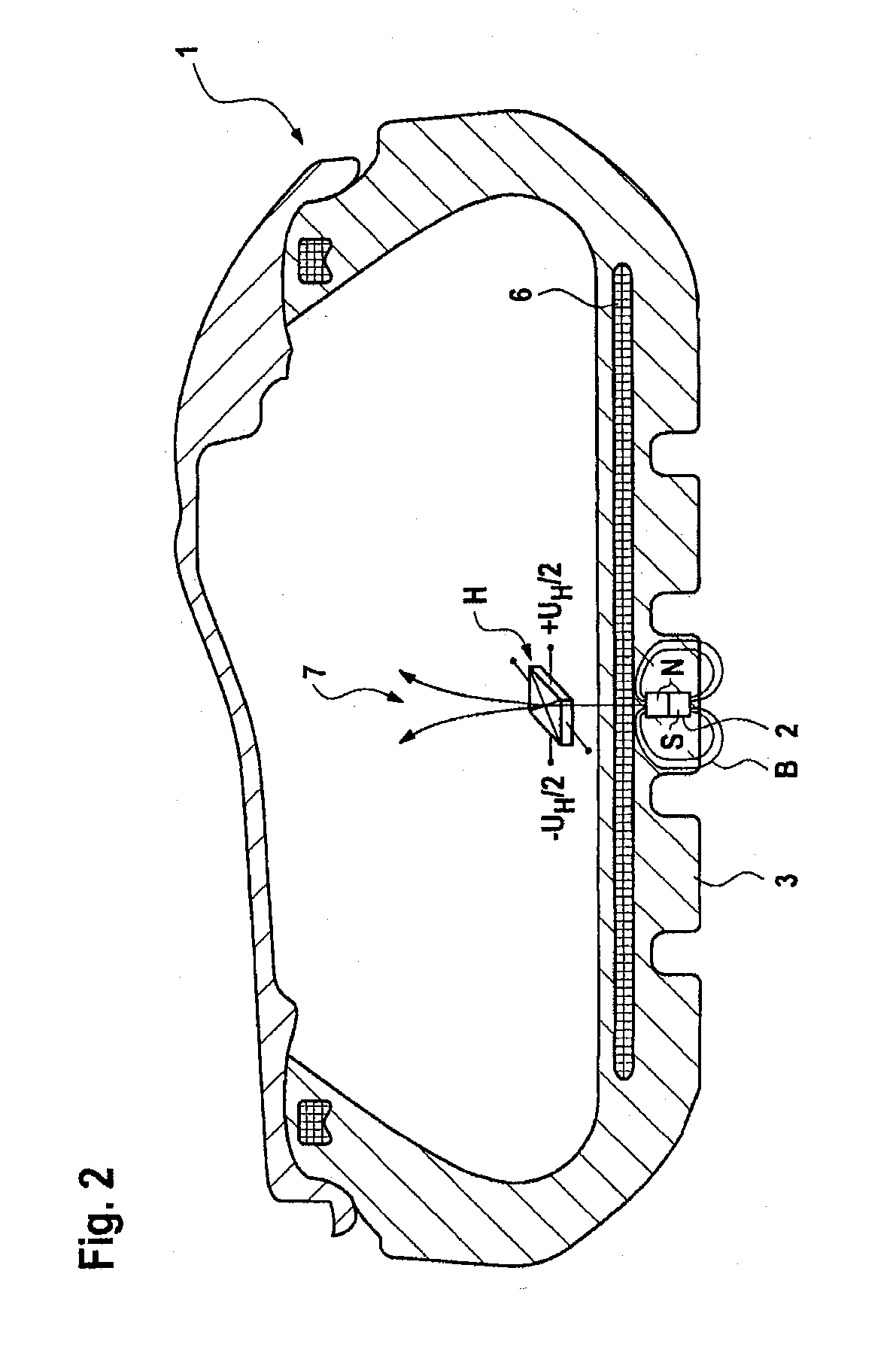
[0061]Likewise, the magnetic circuit can be formed by a permanent magnet 2 or a coil as a magnetic field emitter in the wheel arch and by a Hall sensor H as the magnetic field detector D on the inside of the tire plus a ferromagnetic or diamagnetic body 11 as a field modulator on the outside of the tire (see, for example, third exemplary embodiment).

[0062]For example, one or more ferromagnetic bodies (flux concentrators) is / are placed by the side of the field detector (magnetic field sensor D) to assist the sensing by increasing the flux density.

[0063]The manufacture of a tire according to aspects of the invention is suitable in an optimum way for OEM (original equipment manufacturer) furnishing of tires with means of sensing tire profiles, but is also conceivable for retrofitting. To perform retrofitting, the magnets 2 are, for example, subsequently inserted into position pockets in the profile 3, which are formed during the tire manufacturing process. Alternatively, the position p...


PUM

PropertyMeasurementUnit
magnetic fieldaaaaaaaaaa
distanceaaaaaaaaaa
speedaaaaaaaaaa

Abstract

A method used for determining a profile depth or wear on a tread of a tire of a vehicle, and / or a tire characteristic, a magnetic field being detected by a magnetic field sensor disposed in the interior of the tire, particularly in the area of the tread on the tire interior, or at a distance from the tire, particularly in the area of a wheel housing or a wheel well of the vehicle, the magnetic field being transmitted or changed by at least one indicator element disposed in the tread on the tire exterior. The current wear state of the tread and / or the tire characteristic, particularly a tire type and / or permissible top speed, is determined based on output signals of the magnetic field sensor. The invention further relates to tires.

Description

CROSS REFERENCE TO RELATED APPLICATIONS[0001]This application is the U.S. national phase application of PCT International Application No. PCT / EP2008 / 059625, filed Jul. 23, 2008, which claims priority to German Patent Application No. 10 2007 035 299.0, filed Jul. 27, 2007 and German Patent Application No. 10 2008 028 967.1, filed Jun. 18, 2008, the contents of such applications being incorporated by reference herein.BACKGROUND OF THE INVENTION[0002]1. Field of the Invention[0003]The invention relates to a method with which a profile depth or wear on a tread of a tire of a vehicle and / or a tire characteristic are / is determined in a tire and to a tire.[0004]2. Description of the Related Art[0005]Electronic systems are being increasingly used in modern motor vehicles to improve the safety of the vehicle. For example, inter alia, a correct tire pressure and the current state of the tires, for example the current depth of the tire profile, are aspects of a vehicle which are relevant to sa...

Claims


Application Information

Patent Timeline
Patent Type & Authority Applications(United States)
IPC IPC(8): G01M17/02G01N27/72B60C11/24
CPCG01B7/26Y10T152/10027B60C2019/005
Inventor HEISE, ANDREASKAMMANN, STEFANSCHADE, KAI
Owner CONTINENTAL TEVES AG & CO OHG
Why Eureka
Try Eureka