Re-direction of vapor flow across tubular condensers

a technology of vapor flow and tubular condensers, which is applied in the direction of lighting and heating apparatus, separation processes, laminated elements, etc., can solve the problems of affecting these costs in many cases, and achieve the effect of reducing or even eliminating costs

Active Publication Date: 2010-11-04
UOP LLC
View PDF56 Cites 20 Cited by
  • Summary
  • Abstract
  • Description
  • Claims
  • Application Information

AI Technical Summary

Benefits of technology

[0009]The present invention is associated with the discovery of improvements in heat exchangers comprising tube bundles and particularly internal tubular condensers disposed within vapor-liquid contacting apparatuses such as distillation columns. Aspects of the invention relate to the use of vapor flow-directing devices disposed within columns and surrounding or substantially surrounding (e.g., over a surrounding area except for an inlet for downwardly flowing vapor, a non-condensed vapor outlet, and a condensed liquid outlet) tubes within the column that are used in tube bundles of internal tubular condensers as discussed above. Vapor flow-directing devices can be used, for example, as a “shroud” or a means for protecting all or at least a section, such as a co-current, vapor-liquid contacting section, of the tubes within the column from being directly impacted by the rising vapor that is ultimately cooled on external surfaces of the tubes. Vapor flow-directing devices, by directing vapor, for example, in the downwardly flowing direction over at least the co-current contacting section of tubes therefore allow in this section, vapor and condensed liquid to flow co-currently. This reduces or even eliminates the risk of entrainment of condensed liquid by vapor that, in the absence of the vapor flow-directing device, would normally flow upwardly during contact with the external surfaces of the condenser tubes.

Problems solved by technology

The equipment and utilities required for the supply and removal of heat to and from the column significantly impact these costs in many cases.

Method used


Image

  • Re-direction of vapor flow across tubular condensers
  • Re-direction of vapor flow across tubular condensers
  • Re-direction of vapor flow across tubular condensers

Examples


Embodiment Construction

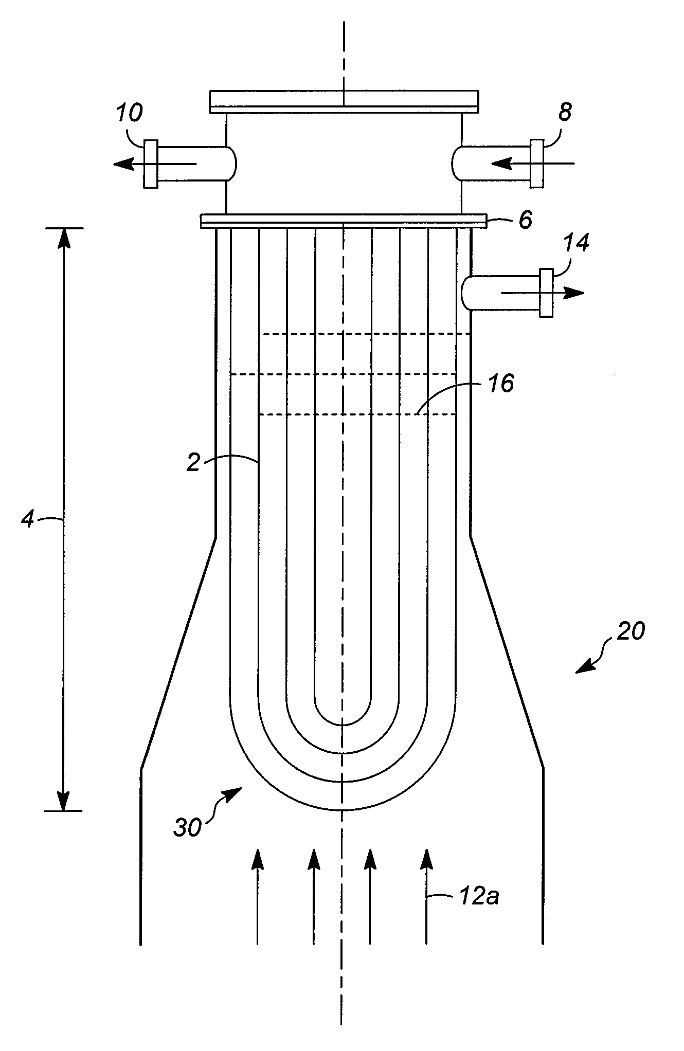
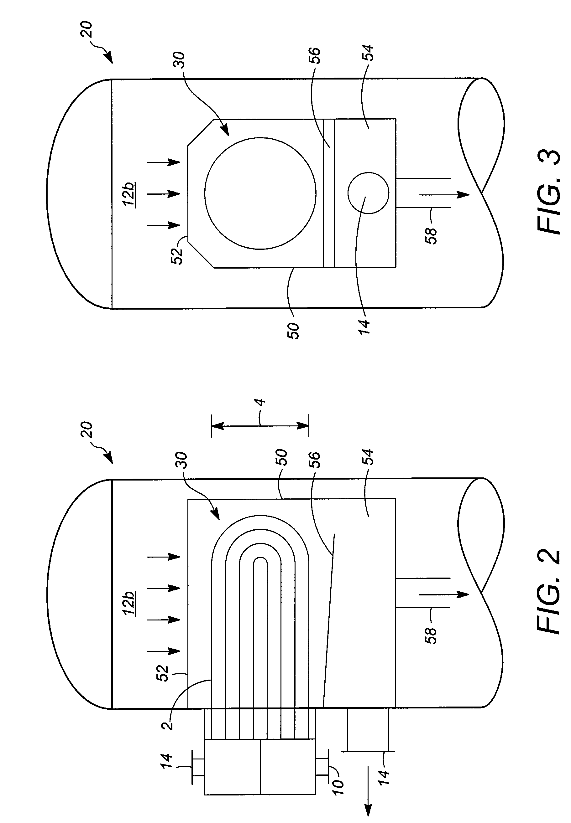
[0050]The invention is associated with improvements in heat exchangers and particularly internal tubular condensers used in vapor-liquid contacting apparatuses such as distillation columns. Internal tubular condensers, often referred to the in art as “column installed” or “stabbed-in” tubular condensers when used to condense vapors generated in distillation, are normally installed in the upper vapor-liquid contacting section of a column. These condensers may be installed either vertically from the top, as shown in FIG. 1 or horizontally from the side, as shown in FIG. 2. References to tubes extending vertically or horizontally are based on their general direction of orientation with respect to a vertically or substantially vertically oriented column in which they are disposed. Therefore, vertically extending tubes will extend, over the majority of their length, in the same general direction as the axis of the column, while horizontally extending tubes will extend, over the majority ...


PUM

PropertyMeasurementUnit
diameteraaaaaaaaaa
heightaaaaaaaaaa
diameteraaaaaaaaaa

Abstract

Vapor flow-diverting devices that re-direct upwardly flowing vapor, for example, in a downward direction across condenser tubes disposed in the upper or top section of a vapor-liquid contacting apparatus, are described. These devices are particularly beneficial in tubular condensers within distillation columns and may be used in combination with other associated equipment (e.g., a deflector plate and divider plate) as well as in combination with the tube surface enhancements to improve the heat transfer coefficient.

Description

FIELD OF THE INVENTION[0001]The invention relates to heat exchangers such as tubular condensers with tubes that may extend horizontally or vertically within a distillation column. The heat exchangers have a vapor flow-directing device to re-direct vapor flow (e.g., in the downward direction) across a section of the condenser tubes to reduce the possibility of entrainment of condensed liquid.DESCRIPTION OF RELATED ART[0002]Heat exchangers are prevalent in refining, petrochemical, and other industrial applications in order to efficiently transfer heat available in one process fluid to another fluid, such that the overall utility requirements are reduced. The advantages of using heat exchangers, for example, to optimize the recovery of heat and thereby minimize the costs associated with outside sources of cooling / refrigeration media (e.g., cooling water) and / or heating media (e.g., fuel gas) are well recognized. The art has continually sought to improve the performance of heat exchange...

Claims


Application Information

Patent Timeline
Patent Type & Authority Applications(United States)
IPC IPC(8): F28B3/00F28F3/00
CPCB01D5/009F28D7/06F28F1/426B01D5/0093F28F9/22B01D5/0009F28F2210/06F28F1/422F28F1/36B01D5/0063F28F13/187F28F1/08F28F1/14F28F2009/226F28F1/24F28F1/42B01D5/0012F28B1/02F28B9/02F28D15/02F28F13/12F28F1/10
Inventor DALY, PHILLIP F.LANKTON, STEVEN P.TUCKER, RAYMOND E.
Owner UOP LLC
Why Eureka
Try Eureka