Seal carrier for a turbomachine, in particular a gas turbine

a turbomachine and seal carrier technology, applied in the field of gas turbines, can solve the problems of low stiffness and hardly improved seal carrier, and achieve the effect of reducing or even eliminating the above disadvantages

Active Publication Date: 2019-10-15
MTU AERO ENGINES GMBH
View PDF11 Cites 1 Cited by
  • Summary
  • Abstract
  • Description
  • Claims
  • Application Information

AI Technical Summary

Benefits of technology

[0005]It is an object of the present invention to provide a seal carrier that reduces or even eliminates the above disadvantages.
[0006]To achieve this object, it is proposed to provide at least one stiffening element on the carrier base, the stiffening element extending along the circumferential direction and at least partially covering the at least one seal member at one of its axial end regions. The partial coverage of an axial end region results in a stiffening element that extends in the circumferential direction and in the radial direction. Thus, it projects radially from the carrier base, forming kind of a circumferential rib. The provision of such a rib-like stiffening element increases the stiffness of the seal carrier, particularly in the circumferential direction. An increased stiffness of the seal carrier makes it also possible, for example, to reduce a running clearance formed between the seal member and an opposite sealing projection of a rotor component because the enhanced stiffness makes it possible to maintain small tolerances. By being at least partially covered, the seal member is protected from damage during installation. This protection is particularly effective when the stiffening element is radially dimensioned to completely cover the seal member.
[0007]In a refinement, it is proposed that a stiffening element be provided on the carrier base at each of its two axial end portions such that the at least one seal member is axially accommodated between the two stiffening elements. Thus, the seal carrier has a stiffening element at each of its two axial ends, so that a seal member accommodated therebetween is even better protected against damage. Furthermore, by providing a second stiffening element, the stiffness of the seal carrier is further enhanced.

Problems solved by technology

The seal carrier exhibits low stiffness, particularly in the circumferential direction, which is hardly improved by the honeycomb seal member because the honeycomb cells themselves are not particularly stiff in the circumferential direction.

Method used


Image

  • Seal carrier for a turbomachine, in particular a gas turbine
  • Seal carrier for a turbomachine, in particular a gas turbine
  • Seal carrier for a turbomachine, in particular a gas turbine

Examples


Embodiment Construction

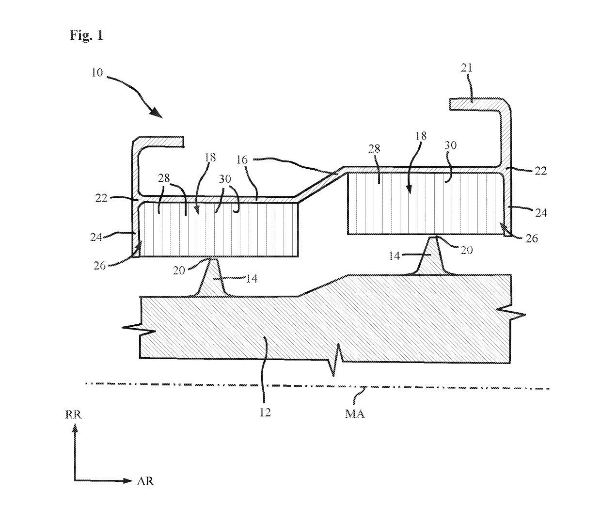
[0027]FIG. 1 shows a seal carrier 10 in simplified schematic cross-sectional view. A possible axis of rotation or machine axis MA of a turbomachine, in particular an industrial gas turbine or an aircraft gas turbine, is indicated by a dash-dot line. Machine axis MA extends in axial direction AR. A rotor component 12, which is shown only schematically here, is located opposite seal carrier 10 in radial direction RR. Rotor component 12 has sealing projections 14, which may also be referred to as sealing fins. Sealing projections 14 extend in radial direction RR toward seal carrier 10. Both the seal carrier 10 and rotor component 12 typically extend also in the circumferential direction about machine axis MA and may be segmented in the circumferential direction.

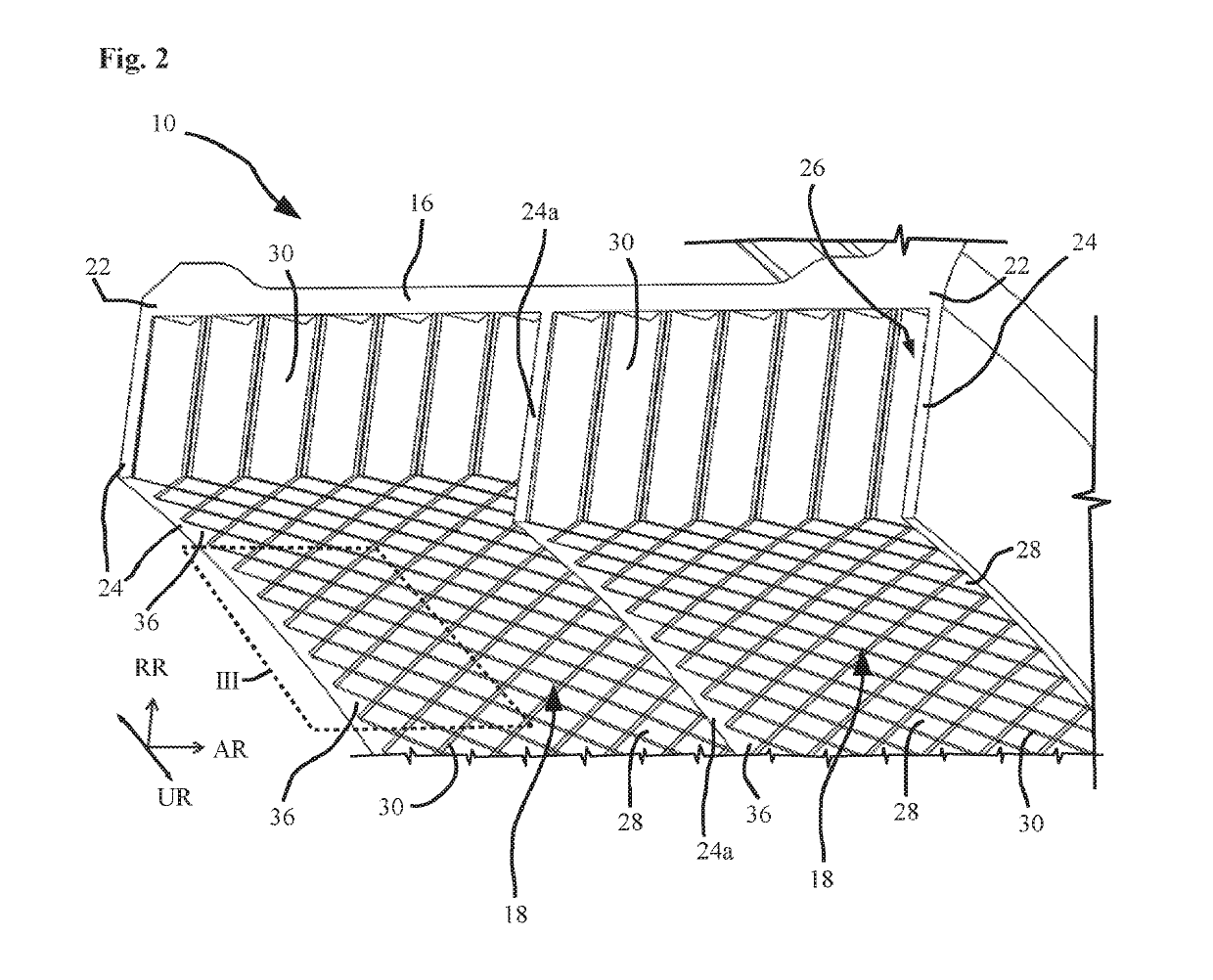
[0028]Seal carrier 10 has a carrier base 16. Preferably, carrier base 16 is a closed ring or an annular sector extending in the circumferential direction about machine axis MA. At least one seal member 18 is provided on carrier ...


PUM

PropertyMeasurementUnit
angleaaaaaaaaaa
angleaaaaaaaaaa
angleaaaaaaaaaa

Abstract

A seal carrier for a turbomachine, in particular a gas turbine, including a carrier base and at least one seal member, the at least one seal member being connected to the carrier base, and the at least one seal member being formed by a plurality of cavities arranged adjacent one another, in particular in a regular fashion, in the circumferential direction and the axial direction, the cavities extending from the carrier base in the radial direction, is provided. At least one stiffening element on the carrier base, the stiffening element extending along the circumferential direction and at least partially covering the at least one seal member at one of its axial end regions is provided.

Description

[0001]This claims the benefit of European Patent Application No. 16163782.2, filed Apr. 5, 2016 and hereby incorporated by reference herein.[0002]The present invention relates to a seal carrier for a turbomachine, in particular an industrial gas turbine or an aircraft gas turbine, the seal carrier including a carrier base and at least one seal member, the at least one seal member being connected to the carrier base, and the at least one seal member being formed by a plurality of cavities arranged adjacent one another, in particular in a regular fashion, in the circumferential direction and the axial direction, the cavities extending from the carrier base in the radial direction.[0003]Directional words such as “axial,”“axially,”“radial,”“radially,” and “circumferential” are taken with respect to the machine axis of the turbomachine or gas turbine, unless the context explicitly or implicitly indicates otherwise.BACKGROUND[0004]Such seal carriers carrying honeycomb seal members are kno...

Claims


Application Information

Patent Timeline
Patent Type & Authority Patents(United States)
IPC IPC(8): F01D11/00F01D11/12B29C64/153B33Y80/00F01D5/02F01D9/04B33Y10/00
CPCB29C64/153F01D11/001F01D11/125F01D11/127F05D2230/22F05D2250/12F05D2250/121B33Y10/00B33Y80/00F01D5/02F01D9/041F05D2220/323F05D2230/31
Inventor KLOETZER, ALEXANDER
Owner MTU AERO ENGINES GMBH
Why Eureka
Try Eureka