Desalination System

Inactive Publication Date: 2010-11-04
HAAG MICHAEL JAMES
View PDF9 Cites 19 Cited by
  • Summary
  • Abstract
  • Description
  • Claims
  • Application Information

AI Technical Summary

Benefits of technology

[0019]In one aspect of this disclosure, although this may not necessarily be the only or indeed the broadest form of this, there is proposed a desalination system comprising a desalination unit submersed at a first depth of saline water d1 (the solute), the desalination unit including at least one semi-permeable membrane separating the saline water from an interior chamber of the desalination unit which is in fluid communication with the atmosphere at the surface of the saline water, a recovery unit also having an interior chamber, which is in

Problems solved by technology

This incidence cannot be demonstrated in the laboratory because it needs a very long tube and, if unsupported, a very strong membrane.
The disadvantage of this method is that the entire volume of feed-water is pumped through the unit

Method used


Image

  • Desalination System
  • Desalination System
  • Desalination System

Examples


Embodiment Construction

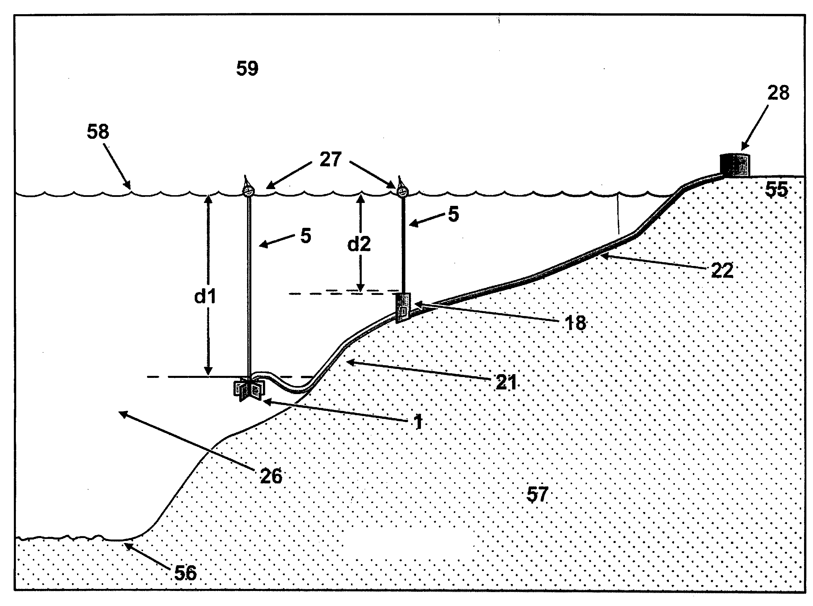
[0162]Referring now to FIG. 10, an exemplary embodiment of a desalination system is illustrated. Specifically, FIG. 10 illustrates a desalination system including a desalination unit 1 submersed at a depth d1 of saline water 26 (the solute), a recovery unit 18 being submersed at a second depth d2 of the saline water 26, which is less than said first depth d1, and a storage unit 28 on the shore 55.

[0163]A first pipeline 21 extends between the desalination 1 and the recovery unit 18, and a second pipeline 22 extends between the recovery unit 18 and the permeate storage facility 28. The recovery unit 18 contains a pump or pumping mechanism 19 which moves permeate to the storage facility 28.

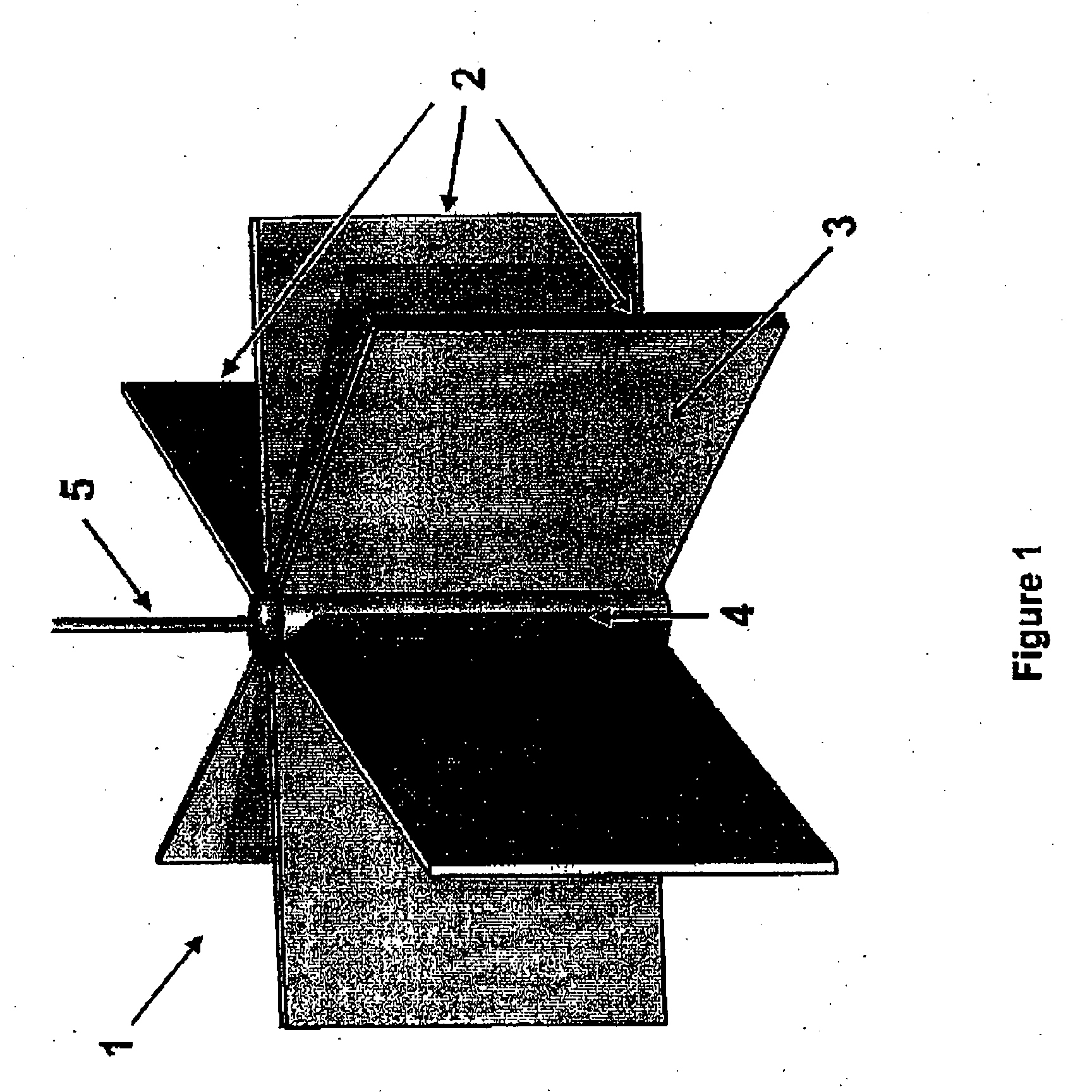
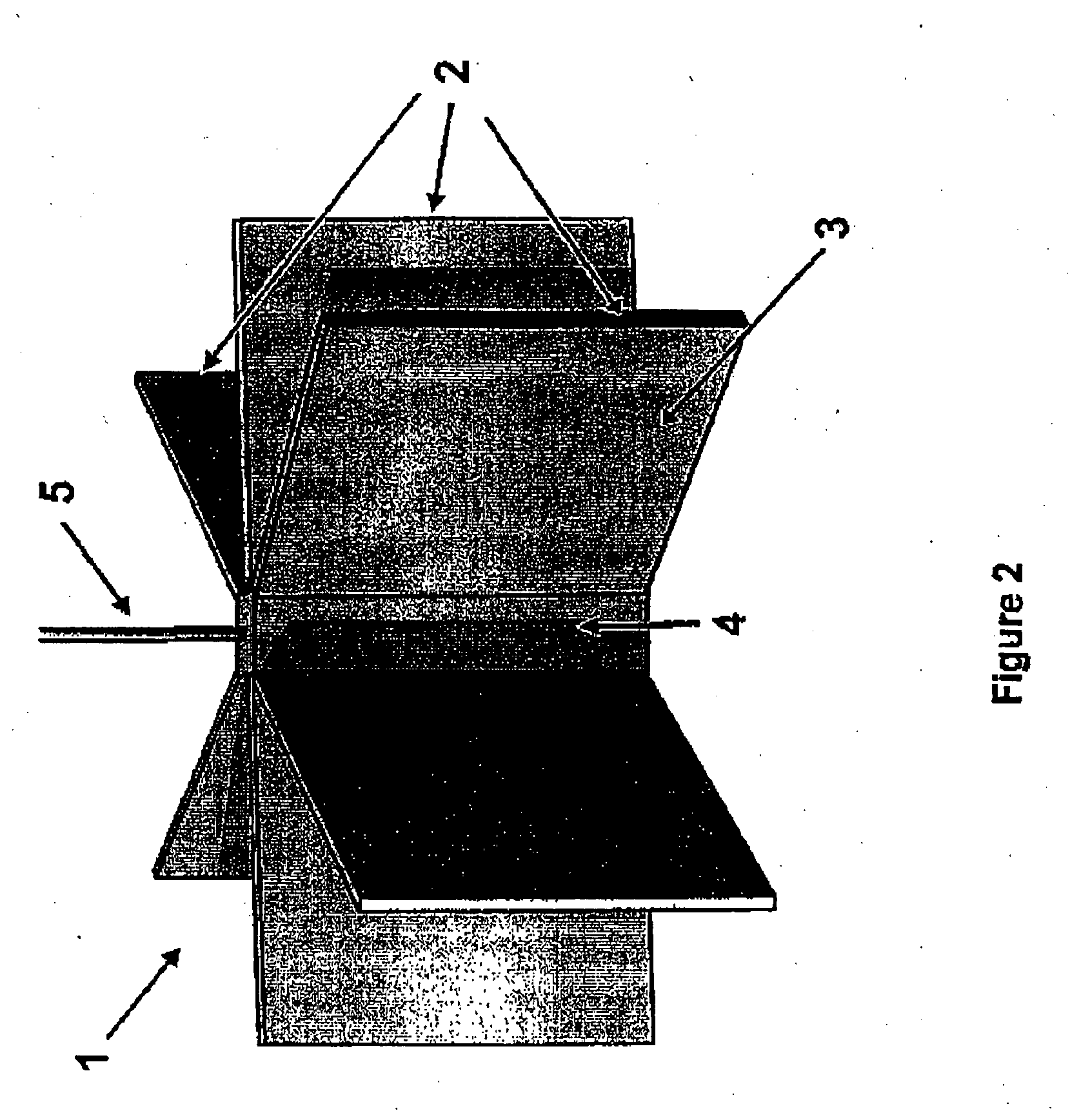
[0164]Referring now to FIG. 1, the desalination unit includes a plurality of semi-permeable membranes 3 supported in panel assemblies 2 depending from a body 4 defining an interior chamber 6. The panels 2 extend radially from the body 4 and the membranes separate the saline water from the interior ch...


PUM


Abstract

A reverse osmotic desalinisation system including a desalinisation unit having at least one semi-permeable membrane in direct contact with a body of saline water at a depth d1, an interior chamber in fluid connection with the saline water via a semi-permeable membrane, the interior chamber being in fluid connection with an atmosphere above a surface of the saline water wherein the depth d1 provides a sufficient hydrostatic pressure p1, being greater than the osmotic pressure to effect at least some desalinisation of the saline water through the semi-permeable membrane to provide a permeate being substantially desalinised water into the interior chamber and a solute outside the interior chamber, such that a solute is able to passively dissipate into the surrounding body of saline water.

Description

FIELD OF THE INVENTION[0001]This disclosure relates generally to a desalination system utilising reverse osmosis and its method of operation.[0002]For the purposes of explanation, reference will be made to use of the present disclosure with respect to a desalination system used in conjunction with a body of oceanic saline water. It would be understood, however, that the disclosure is not necessarily limited to use with seawater instead any natural or man-made body of sufficiently deep brackish water may be utilised.BRIEF DESCRIPTION OF THE PRIOR ART[0003]In this specification unless the contrary is expressly stated, where a document, act or item of knowledge is referred to or discussed, this reference or discussion is not to be construed as an admission that the document, act or item of knowledge or any combination thereof was at the priority date, publicly available, known to the public, part of common general knowledge; or known to be relevant to an attempt to solve any problem wi...

Claims


Application Information

Patent Timeline
IPC IPC(8): C02F1/44
CPCB01D61/025B01D61/08B01D63/08C02F2103/08B01D2315/06C02F1/441B01D63/082Y02A20/131
Inventor HAAG, MICHAEL JAMES
Owner HAAG MICHAEL JAMES
Why Eureka
Try Eureka