35kV Rubber Molded Fused Vacuum Interrupter

a vacuum interrupter and rubber molded technology, which is applied in the direction of high-tension/heavy-dress switches, air-break switches, electrical equipment, etc., can solve the problems of damage to the fuse assembly, inability to design full-range fuses, and inability to meet the physical size of the fuse, and the limiting factor in the design of these full-range fuses is the overall length

Inactive Publication Date: 2010-11-04
THOMAS & BETTS INT INC
View PDF28 Cites 5 Cited by
  • Summary
  • Abstract
  • Description
  • Claims
  • Application Information

AI Technical Summary

Benefits of technology

[0014]In accordance with the present invention, a high voltage, preferably 35 kV, rubber molded fused vacuum interrupter assembly for protecting an electrical circuit from fault currents is provided. The assembly includes one or more vacuum fault interrupters; one or more current limiting fuses; one or more sensing modules, at least one control module and, optionally, a controller. Each of the vacuum fault interrupters is contained in a molded insulating structure and each of the current limiting fuses is encapsulated in a rubber molding. For each phase of the electrical circuit, a vacuum fault interrupter and a current limiting fuse are connected in series. The vacuum fault interrupter interrupts low current faults and the fuse operates to protect against high current faults in a high voltage electrical power line. A single-phase electrical circuit would have one vacuum fault interrupter and one current limiting fuse. A three-phase electrical circuit would have three vacuum fault interrupters and three current limiting fuses.
[0015]Each of the sensing modules measures current passing through one of the vacuum fault interrupters and sends a current measurement signal to the control module. For three-phase systems, a separate control module can be used to control the interrupter for each phase or a single control module can be used to control the interrupters for all three of the phases. A time / current characteristic curve for each of the one or more interrupters is programmed in the control module and used to calculate the predetermined high voltage setting. When a current measurement signal equal to a predetermined high voltage setting is measured, the control module opens or trips the interrupter.
[0016]The high voltage rubber molded fused vacuum interrupter assembly can also include a controller for monitoring one or more of the control modules and for reprogramming the predetermined high voltage setting for each of the one or more interrupters. Each of the vacuum fault interrupters has a predetermined high voltage setting and each of the one or more current limiting fuses has a rated interrupting current. The rated interrupting current is greater than the predetermined high voltage setting so that the interrupter will trip before the melting point of the fuse is reached under operating conditions.
[0017]The one or more vacuum fault interrupters are individually controlled by one or more actuators. Each actuator switches one of the interrupters from a closed position, wherein current passes through the interrupter to an open (or “tripped”) position, wherein current does not pass through the interrupter. Preferably, the one or more actuators and at least one control module for operating the one or more actuators are contained in a mechanism housing.
[0018]A preferred high voltage rubber molded fused vacuum interrupter assembly is used for protecting a three-phase electrical circuit from fault currents. The assembly includes: three vacuum fault interrupters, three actuators, three sensing modules, at least one control module and three current limiting fuses. One control module can be used to control all three interrupters or each interrupter can have a dedicated control module. The current limiting fuses are individually encapsulated in a rubber molding and each of the vacuum fault interrupters is contained in a molded insulating structure. A time / current characteristic curve based on the characteristics of the fuse is programmed in the control module(s) for each of the vacuum interrupters and used to calculate a predetermined high voltage setting based on the design of the circuit. The three actuators individually control the vacuum fault interrupters and switch each interrupter from a closed position, wherein current passes through the interrupter to an open position, wherein current does not pass through the interrupter. The sensing modules measure current passing through each of the vacuum fault interrupters and send a current measurement signal to the control module.
[0019]One vacuum fault interrupter and one current limiting fuse are connected in series for each phase of the three-phase electrical circuit. The current limiting fuse has a rated interrupting current that is greater than the predetermined high voltage setting of the interrupter for each phase. When a voltage equal to the predetermined high voltage setting for one of the interrupters is measured, the control module opens at least one of the interrupters. The vacuum fault interrupter interrupts low current faults and the fuse operates to protect against high current faults in each phase of the three-phase electrical circuit. The assembly can also include a controller for monitoring the control module or control modules and for reprogramming the predetermined high voltage settings of the interrupters.

Problems solved by technology

However, such devices do not current or energy limit and the rubber molded fuses that are currently available have been found to be unacceptable for such high voltage applications.
Modern full-range fuses are “self-protecting,” meaning that they melt under overload conditions before any components in the fuse can overheat and cause damage to the fuse assembly.
The limiting factor in the design of these full-range fuses is the physical size of the fuse, especially the overall length.
While it is possible to rubber mold full-range, current-limiting fuses suitable for use at 35 kV in much the same manner as fuses used for voltages below 23 kV in order to provide dead-front current-limiting protection, the length of such high voltage fuses, which can be in excess of 35 inches, is prohibitive.
Current-limiting backup fuses are not self-protecting, meaning that if subjected to an overload condition, the fuse will overheat and its components will be damaged.
While backup fuses suitable for 35 kV systems are of a desirable length for molding, they have not been rubber molded for use in dead-front applications because the rubber encapsulation restricts heat loss.
The build up of heat inside the rubber molded encapsulation makes components run hotter at lower currents and makes it very difficult to provide the overload protection needed to keep the components of the fuse and the rubber molded encapsulation from overheating and being damaged.
The melting time versus current curve for these thermal devices (expulsion fuses and breakers) shows that an unacceptably large current-limiting fuse would be required in order to prevent the fuse from overheating.
This would result in an inconveniently long fuse with undesirable current and energy limiting characteristics.
Putting a ground plane (needed to make the device dead-front) so close to the fuse elements, which are at high potential, creates stress and can lead to corona (also known as partial discharge).
Over time corona can cause the elements to deteriorate and the fuse to fail.
However, after the fuse interrupts, full voltage may appear across that gap.
Prior art devices have not been successful in creating a Faraday cage with a gap that can withstand 35 kV indefinitely.
Attempts to provide a device for 35 kV systems have been unsuccessful.

Method used


Image

  • 35kV Rubber Molded Fused Vacuum Interrupter
  • 35kV Rubber Molded Fused Vacuum Interrupter
  • 35kV Rubber Molded Fused Vacuum Interrupter

Examples


Embodiment Construction

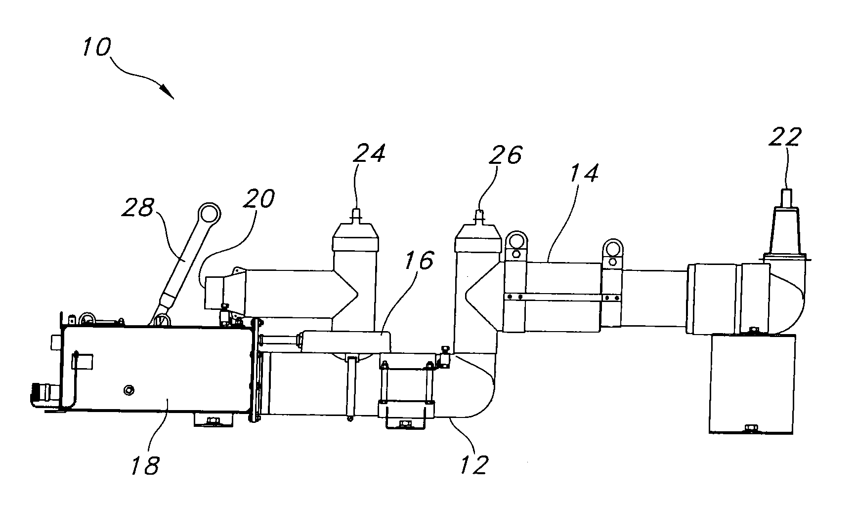
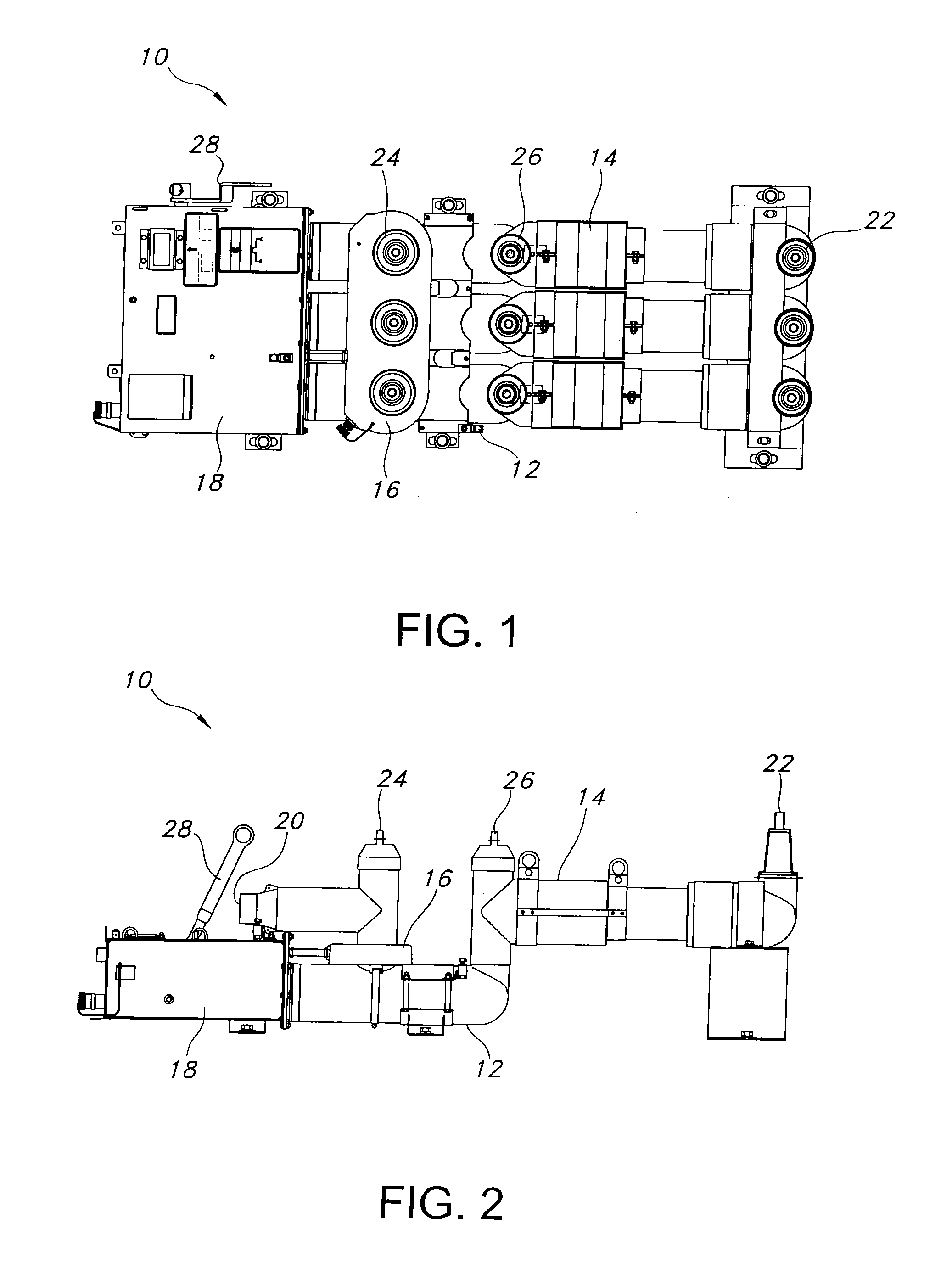
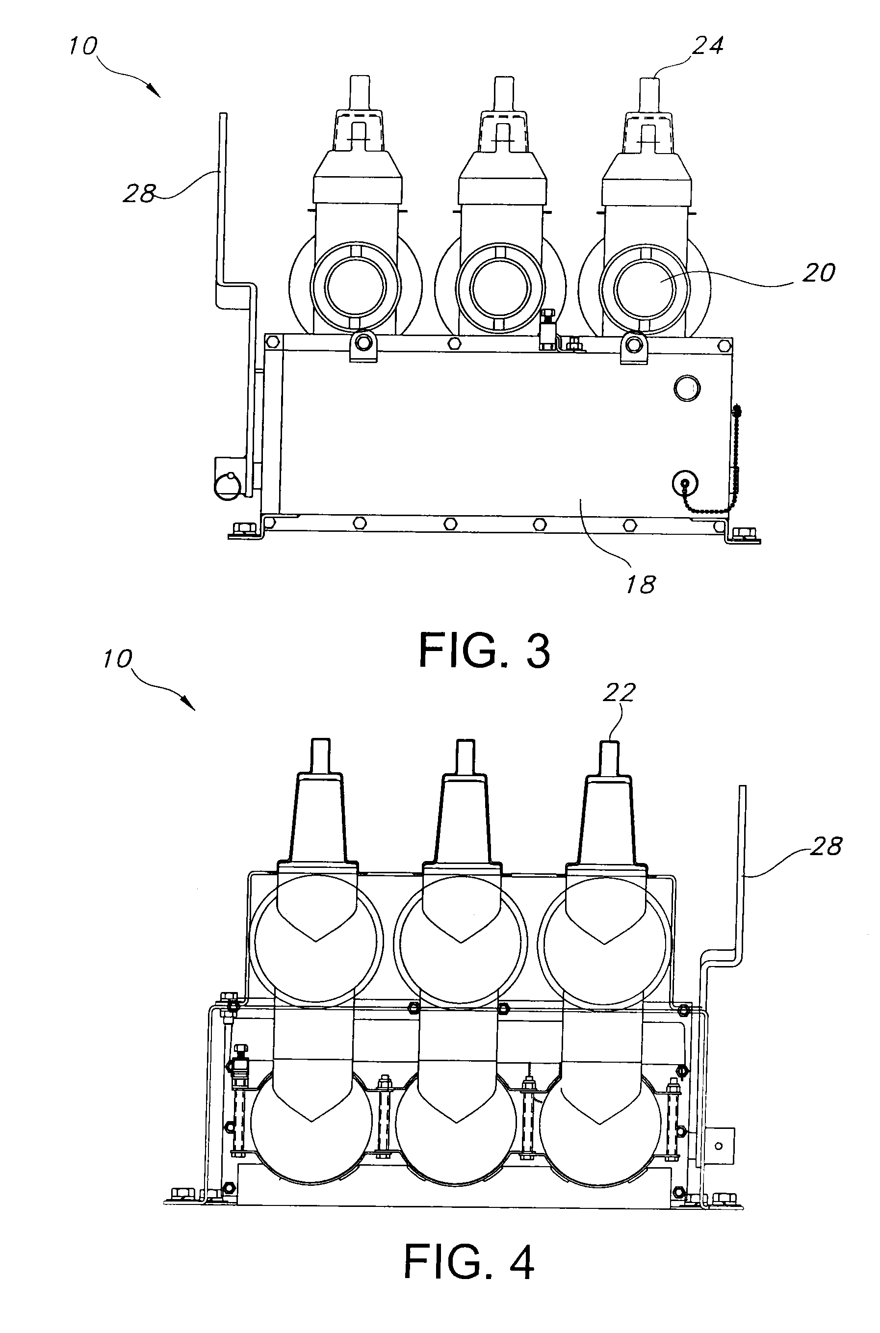
[0028]The present invention is directed to a 35 kV rubber molded fused vacuum interrupter assembly, which combines a rubber molded vacuum interrupter with a current-limiting backup fuse. This allows the current-limiting backup fuse to be rubber molded and creates a compact, fully “dead-front” protective device suitable for 35 kV systems. The device provides not only overload and fault protection, but also current and energy limiting protection. As used herein, the term “dead front” means that there are no voltages present on the operating side of the equipment.

[0029]The high voltage rubber molded fused vacuum interrupter assembly includes one or more vacuum fault interrupters in a molded insulating structure and one or more current limiting fuses encapsulated in a rubber molding. The vacuum interrupter assembly can be installed on a single-phase high voltage line or a three-phase electrical circuit (also referred to herein as a three-phase system). For the single-phase, high voltage...


PUM


Abstract

A high voltage, preferably 35 kV, rubber molded fused vacuum interrupter assembly for protecting an electrical circuit from fault currents. The assembly includes one or more vacuum fault interrupters; one or more current limiting fuses; one or more sensing modules and a control module. Each of the vacuum fault interrupters is contained in a molded insulating structure and each of the current limiting fuses is encapsulated in a rubber molding. For each phase of the electrical circuit, a vacuum fault interrupter and a current limiting fuse are connected in series. The sensing modules measure the current in the lines. The vacuum fault interrupter interrupts low current faults and the fuse operates to protect against high current faults in a high voltage electrical power line. A three-phase electrical circuit would have three vacuum fault interrupters and three current limiting fuses.

Description

[0001]This application claims priority from provisional application Ser. No. 61 / 214,874, filed on Apr. 29, 2009, which is incorporated herein in its entirety.FIELD OF THE INVENTION[0002]The present invention relates to high voltage vacuum interrupters. In particular, the present invention relates to dead front, rubber molded, fused, vacuum interrupter assemblies that can be used in high voltages systems up to 35 kV.BACKGROUND OF INVENTION[0003]Dead-front current and energy limiting fault protection is commonly provided in systems with voltages of up to 23 kV using rubber molded, full-range, current-limiting fuses. Dead-front overload and fault protection in 35 kV systems can be provided using molded vacuum interrupters (“MVIs”). However, such devices do not current or energy limit and the rubber molded fuses that are currently available have been found to be unacceptable for such high voltage applications.[0004]Modern full-range fuses are “self-protecting,” meaning that they melt un...

Claims


Application Information

Patent Timeline
Patent Type & Authority Applications(United States)
IPC IPC(8): H01H33/66
CPCH01H33/66207H01H2033/6623H01H9/10H01H33/6661
Inventor GARDNER, DANIEL LEE
Owner THOMAS & BETTS INT INC
Why Eureka
Try Eureka