Fluid warmer with switch assembly

a technology of switch assembly and fluid, which is applied in the direction of ohmic resistance heating, electric heating of furnaces, furnaces, etc., can solve the problems of reducing the temperature of fluid at room temperature, consuming fraction of oven capacity, and consuming longer to heat the entire volume, so as to reduce the overall footprint of presence and temperature sensors on the support surface, and quickly and accurately measure the temperature of items. , the effect of accurate reading of items

Active Publication Date: 2010-11-04
ENTHERMICS MEDICAL SYST
View PDF52 Cites 20 Cited by
  • Summary
  • Abstract
  • Description
  • Claims
  • Application Information

AI Technical Summary

Benefits of technology

[0020]Thus, a fluid warmer and a switch assembly are disclosed that are able to both detect the presence and the temperature of an item, such as a bag of fluid, on a contact surface of the switch assembly. The portion of the switch assembly which directly contacts the item may be made of a highly thermally conductive material, such as copper, so that one or more thermocouples embedded below the contact surface may quickly and accurately measure the temperature of the item on the switch assembly.
[0021]Notably, the switch assembly integrates the thermocouple into the same part of the structure that detects the presence of the item. As a result, the overall footprint of the presence and temperature sensors on the support surface is minimized. Further, as the thermocouple in the switch assembly is thermally isolated from the support surface of the fluid warmer (i.e., the thermocouple is not directly supported by the support surface, but is rather located in the heat conducting member of the switch assembly which is isolated from the heated support surface), the thermocouple obtains a more accurate reading of the item on the fluid warmer and not the temperature of the heated support surface.

Problems solved by technology

However, many of these fluid degrade at room temperature when outside of a body.
However, more frequently, only a fraction of the capacity of the oven is utilized.
This under-utilization of the volume of the oven means that it may take longer to heat the entire volume up to the desired temperature and that energy is lost when the oven is at less than capacity.

Method used


Image

  • Fluid warmer with switch assembly
  • Fluid warmer with switch assembly
  • Fluid warmer with switch assembly

Examples


Embodiment Construction

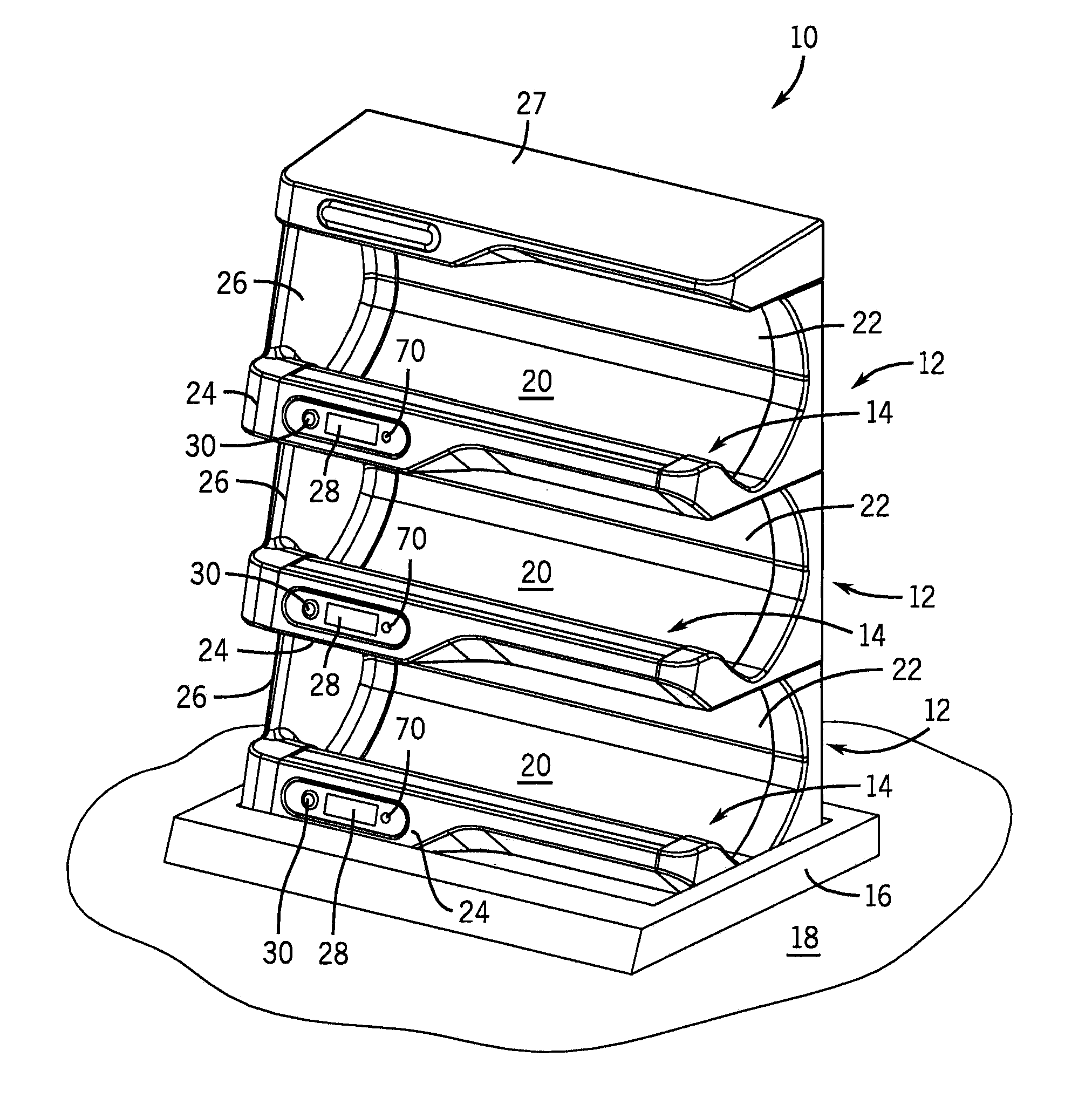
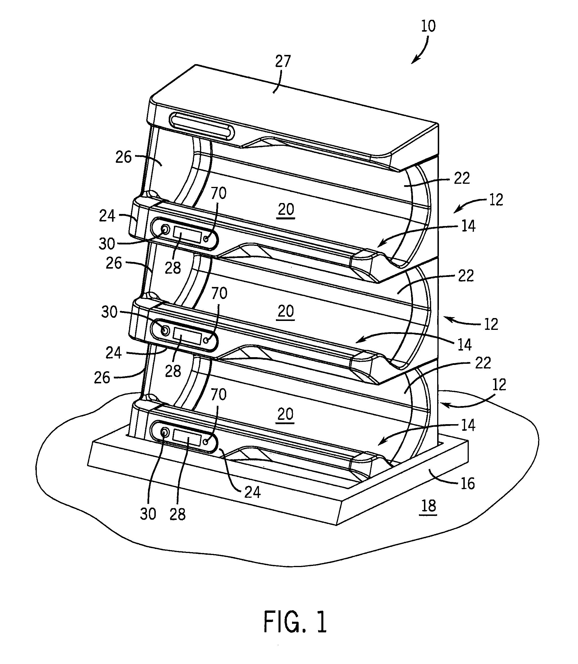
[0039]Referring first to FIG. 1, a stacked assembly 10 is composed of a number of modular fluid warmers 12. As shown, the modular fluid warmers 12 are stacked three high, thus providing three shelves 14 for the placement of the containers. Although the stacked assembly 10 is shown as containing three modular fluid warmers 12, it should be appreciated that the stacked assembly 10 can include one or more modular fluid warmers 12. As shown in FIG. 1, the stacked assembly 10 is docked in a countertop pedestal 16 that rests on the surface of a table 18.

[0040]Each of the modular fluid warmers 12 form shelves 14 having support surfaces 20 for the placement of a container (not shown), such as a bag or bottle, that is filled with fluid. As can be seen best in FIG. 3, the support surface 20 is essentially C-shaped for receiving the bag or bottle. Although essentially C-shaped, the support surface 20 also has a portion that is flat with a bend so as to better receive bottles having a generally...


PUM


Abstract

A fluid warmer is disclosed. The fluid warmer includes a support surface, a heating element configured to selectively heat the support surface, and a switch assembly extending through the support surface. The switch assembly includes a switch, a movable switch plate, and a thermocouple. The switch has at least two states, one of which indicates the presence of an item on the support surface. The movable switch plate operably links to the switch to move the switch between the states and further includes a contact surface that contacts an item placed on the support surface. One or more thermocouples are embedded in the movable switch plate below the contact surface. The movable switch plate comprises a material having a thermal conductivity that permits the thermocouple(s) embedded in the switch plate to measure a temperature of an item placed on the support surface within a predetermined period of time.

Description

CROSS-REFERENCE TO RELATED APPLICATION[0001]This patent application is a continuation-in-part of U.S. patent application Ser. No. 12 / 208,166 filed on Sep. 10, 2008, the disclosures of which is hereby incorporated by reference as if set forth in its entirety herein.STATEMENT OF FEDERALLY SPONSORED RESEARCH OR DEVELOPMENT[0002]Not applicable.BACKGROUND OF THE INVENTION[0003]This invention relates to the heating of a fluid disposed in a container. In particular, this invention relates devices and methods for the efficient heating of a fluid prior to its introduction into a body.[0004]During medical care, it may be necessary to introduce a fluid into a human body intravenously. Such fluids may include, for example, blood, saline solution, antibiotic solution, and the like. Prior to administration, these fluids are usually stored in containers such as bags or bottles.[0005]However, many of these fluid degrade at room temperature when outside of a body. Since the demand for many of these ...

Claims


Application Information

Patent Timeline
Patent Type & Authority Applications(United States)
IPC IPC(8): H05B3/00H05B1/02
CPCA61M5/445A61M5/44
Inventor HANSEN, WILLIAM J.SMITH, TERENCE T.
Owner ENTHERMICS MEDICAL SYST
Why Eureka
Try Eureka