
Thermal Energy Radiance Expander

Inactive Publication Date: 2010-11-04
GRAVINA MATTEO BONIFACIO
View PDF23 Cites 7 Cited by
  • Summary
  • Abstract
  • Description
  • Claims
  • Application Information

AI Technical Summary

Benefits of technology

[0010]The present invention solves the problems neglected by prior art by tackling the formation of vortexes in thunderstorms. The object of the present invention is to dismantle centrifugal force emanating from below of super cells that turn into tornados. The advantage of the present invention over prior art is the head on confrontation of vortexes. By driving a vehicle to the presence of weather conditions where tornados are problem and by releasing a projectile design especially for tornados.
[0011]According to the present invention, the objective is to drive near the presence of a super cell. Since super cells are the direct precursor of tornados through thunderstorms the possibilities of a tornado evolves. The use of a vehicle mounted with a supportive platform and modified with a projectile is use. The large vehicle carries a platform design to carry heavy equipment has an attach section that carries a large platform. Below the platform are containers and other equipment use to carry an operation on a surgical strike on a tornado. Containers carrying liquefied gas is use to load a projectile missile with this gas. Tornado presence detected on the carry on module a projectile is loaded then with liquefied gas. As the tornado matures, the missile is made live in the control module and fired into the tornado. As the tornado turns the missile object is to hit on section of the vortex.
[0012]An object of the present invention is to dismantle the vortex by disorienting the centrifugal force. The ferocity of the exploding projectile is that as to forcefully neglect the continuance of the vortex. An advantage of the present invention over prior art is that special design structures, warning system, and shelters, is the direct confrontation and elimination of tornado vortexes.
[0013]In conclusion the lack of prior art in confronting a tornado head on does not eliminate the birth and continuity of a tornado. The present invention serves as deterrent.DETAILED DESCRIPTION OF THE PREFERRED EMBODIMENT
[0014]A system process use for the direct engagement of tornadic anomaly with the use by employing a ground crew, a mobile weather chasing vehicle, and a missile battery system that when made active is use to hit a vortex. In the following detailed description, various specific details are set forth in order to provide clarity and understanding of the present invention. Nevertheless, it will be obvious to one of ordinary skill in the art that that these specific details need not be used to practice the present invention. The complexities of the present invention entail people skill in the art as well various disciplines to use commonly the present invention as specifically intended to confront tornadic activities. The forward description is for use with intended present technology.
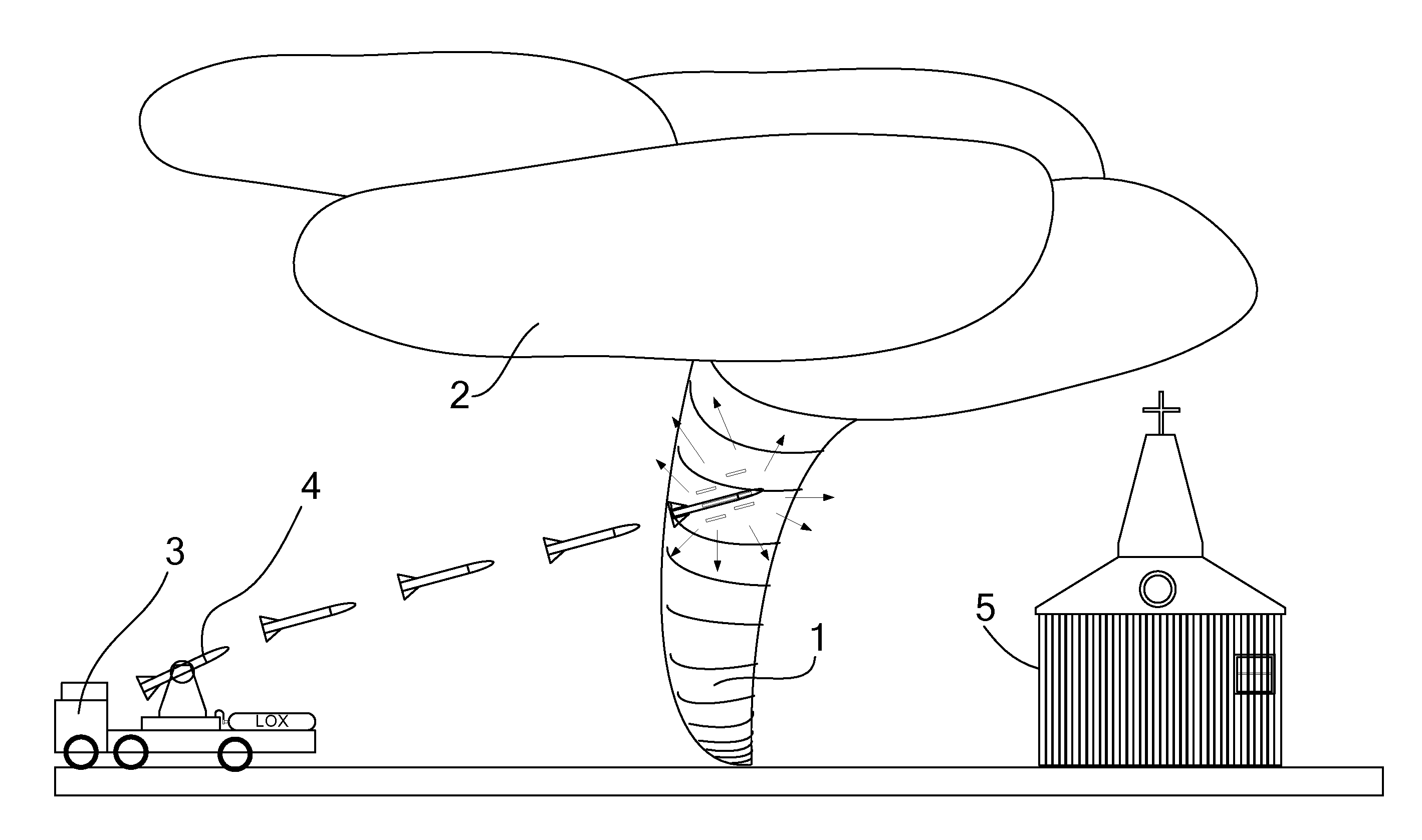
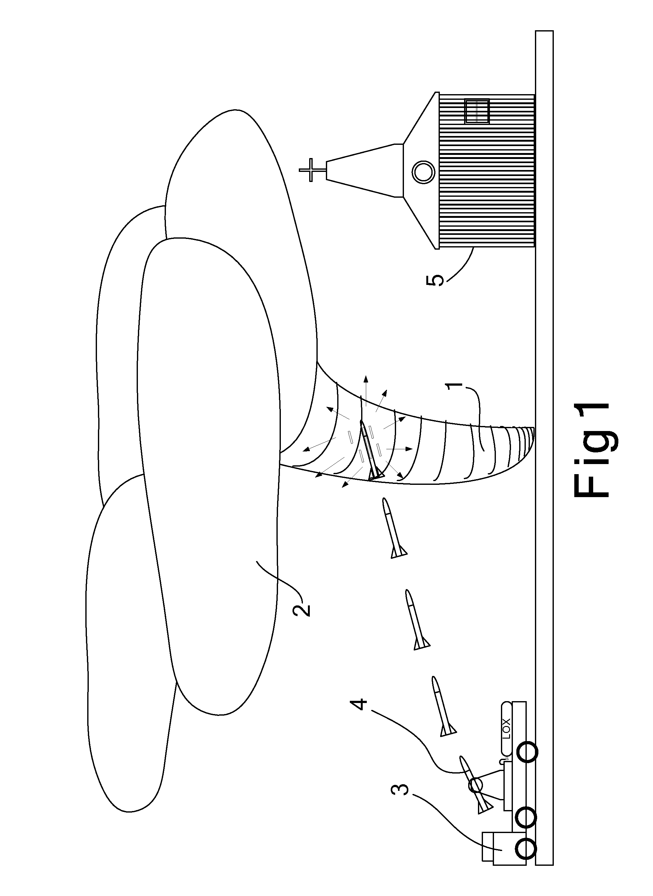
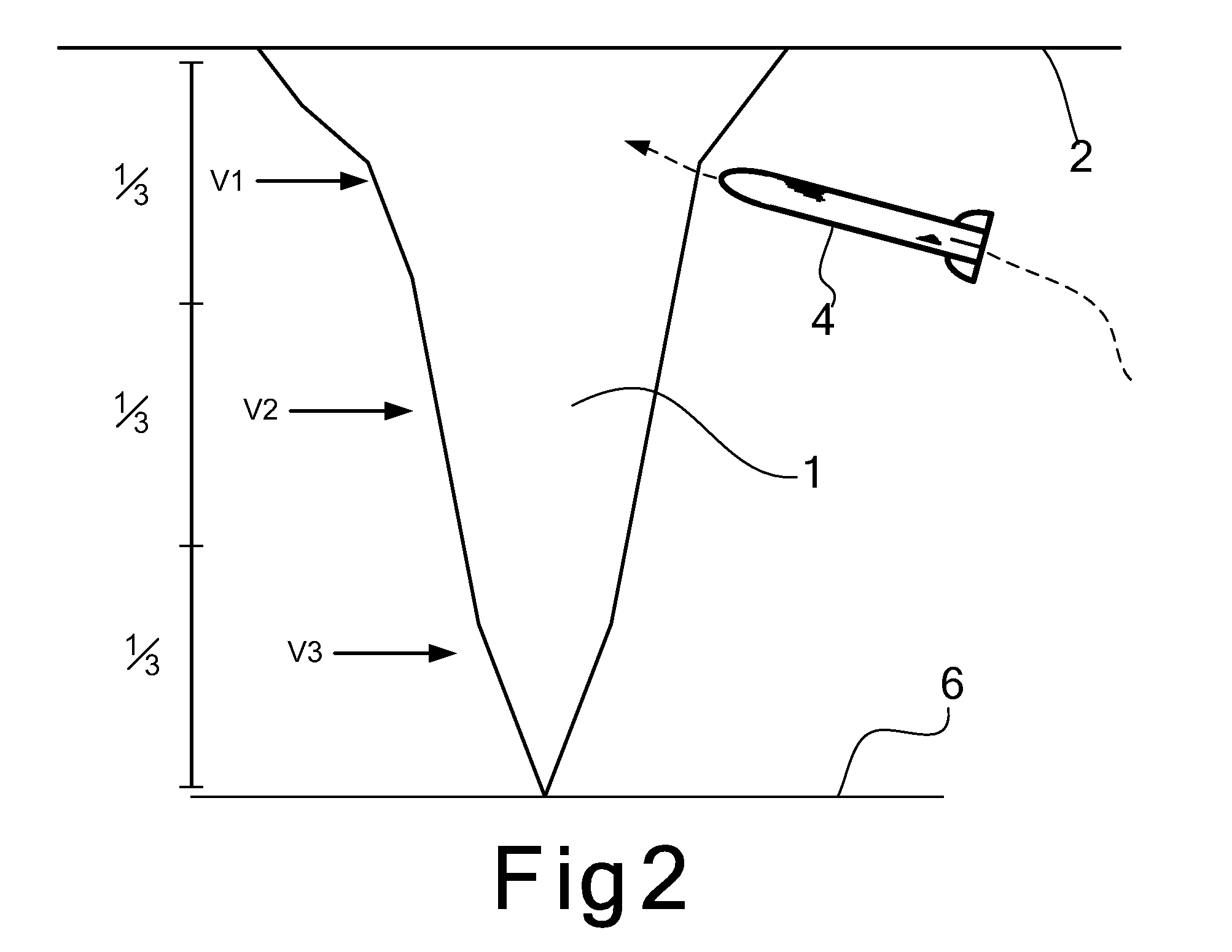
[0015]FIG. 1 is a side view of the mobile launcher (3) deploying the missile (4) as a cloud from above creates a tornado (1). The deploying missile (4) is set to engage head-on the tornado (1) before heading toward a building (5). Since tornados create, some of the highest wind gusts on earth the missile (4) is design with a high impulse also know in the art as ISP. Further details on comparing and contrasting tornado wind gusts to explosives technology are discuss in preceding tables. In FIG. 2 a closer look at the moments leading to the eventual engagement are portrait. As always below the cloud (2) is a surging tornado (1) twisting on its own axis, as the live missile (4) is about to hit the outer area of the tornado (1). A fully developed tornado (1) is shown as the vortex has touched the ground (6). FIG. 2 shows a fully developed tornado (1) with three sectionalize areas. The first section is V1, which is the vortex-to-cloud bridge; the second section is V2 that is the middle body, and V3, which is the vortex-to-ground bridge. The preferred intent of the present invention is to hit the tornado in the V1 section.

Problems solved by technology

In conclusion the lack of prior art in confronting a tornado head on does not eliminate the birth and continuity of a tornado.

Method used


Image

  • Thermal Energy Radiance Expander
  • Thermal Energy Radiance Expander
  • Thermal Energy Radiance Expander

Examples


Embodiment Construction

[0014]A system process use for the direct engagement of tornadic anomaly with the use by employing a ground crew, a mobile weather chasing vehicle, and a missile battery system that when made active is use to hit a vortex. In the following detailed description, various specific details are set forth in order to provide clarity and understanding of the present invention. Nevertheless, it will be obvious to one of ordinary skill in the art that that these specific details need not be used to practice the present invention. The complexities of the present invention entail people skill in the art as well various disciplines to use commonly the present invention as specifically intended to confront tornadic activities. The forward description is for use with intended present technology.

[0015]FIG. 1 is a side view of the mobile launcher (3) deploying the missile (4) as a cloud from above creates a tornado (1). The deploying missile (4) is set to engage head-on the tornado (1) before headi...


PUM


Abstract

A specially design missile system use for hindering the centrifugal forces inside vortexes commonly known as tornados. The missile system composed of a typical modified vehicle with a design platform. The platform is design of the insides of a platform that contains liquid and compressed gas. A command and control module and a projectile missile system complement above the platform. When a super cell appears and probable starting of tornado activity commences the Thermal Energy Radiance Expander system is send over to the targeted area. As the initial start of the tornado commences the vehicle and whole system is sent to the target area. The missile is then loaded with the gaseous element turn live and launch on to the target. The missile control through the command module explodes intentionally at the side of the vortex. The aim of the system is to break and hinder further activity of the vortex hence terminating tornado.

Description

CROSS REFERENCE TO RELATED APPLICATIONS[0001]This application claims the benefit of the U.S. Provisional Application Ser. No. 60 / 766,222, filed Dec. 31, 2005. For “THERMAL ENERGY RADIANCE EXPANDER” which is hereby incorporated by reference herein.FIELD OF THE INVENTION[0002]The invention relates to a method and system of diverting the start of vortex anomalies herein known as tornados. A method of using the system process which hinder cyclonic vortexes from birth, growth, or continuity. The system itself is a projectile design to contest the ferocity of tornado vortexes from bridging between super-cells to ground. A method and system contemplating the continuity of tornado activity by inhibiting engagement cloud to ground bridge.BACKGROUND OF THE INVENTION[0003]Energy in motion is part of the life cycle. Energy deliverance from our sun provides energy transference all around our planet. Planetary mechanics and solar energy provide our planet with climates. In turn, climates promote ...

Claims


Application Information

Patent Timeline
IPC IPC(8): F42B12/20
CPCA01G15/00F42B12/52F42B12/205
Inventor GRAVINA, MATTEO BONIFACIO
Owner GRAVINA MATTEO BONIFACIO
Learn More