Light source apparatus

a technology of light source and illumination light, which is applied in the direction of electric variable regulation, process and machine control, instruments, etc., can solve the problems of large fluctuation of light level of light output toward illumination region, change in color temperature of light to be output, and inability to achieve uniform output, stably output, and maximize the light level of illumination light emitted

Inactive Publication Date: 2010-11-04
OLYMPUS CORP
View PDF6 Cites 84 Cited by
  • Summary
  • Abstract
  • Description
  • Claims
  • Application Information

AI Technical Summary

Benefits of technology

[0028]By doing so, since the pulsed-lighting phase range is controlled on the basis of the light level detected by the optical sensor, regardless of the emission characteristics of the illumination light by the light source devices, it is possible to maximize the light level of the illumination light emitted from the light-guide portion.
[0029]In other words, by performing control on the basis of the light level detected by the optical sensor, it is possible to set the preceding light-out phase range and the succeeding light-out phase range before and after the pulsed-lighting phase range. Therefore, it is possible to make the illumination light emitted from the light source devices incident on the light entrance surface of the light-guide portion reliably.
[0030]The light source apparatus according to the present invention affords an advantage in that it is possible to adjust the light level of the emitted illumination light and stably output illumination light with a high light level by controlling the pulsed-lighting phase range; and to absorb the variation between the rotation phase of the light-guide portion and the emission phase of illumination light to output the illumination light efficiently by ensuring light-out phase ranges before and after the pulsed-lighting phase range.

Problems solved by technology

However, in the method in which the current value to be supplied to the light-emitting devices is changed, there has been a problem in that the color temperature of the light output toward the illumination region is changed.
In other words, since the light-emitting devices have a characteristic whereby the color temperature of the emitted light changes in accordance with the current value supplied thereto, in the method in which the light level is adjusted by changing the current value, there has been a problem in that the color temperature of the light to be output is changed.
On the other hand, in the method in which the pulse width is changed, there has been a problem in that the fluctuation of the light level of the light output toward the illumination region becomes large.
In other words, there has been a problem in that, since the rate of jitter becomes higher, the fluctuations of the light level become large depending on the light emission cycle, and the fluctuation is perceived as a flickering.

Method used


Image

  • Light source apparatus
  • Light source apparatus
  • Light source apparatus

Examples


first embodiment

[0048]A first embodiment of the present invention will be described below with reference to FIGS. 1 to 4.

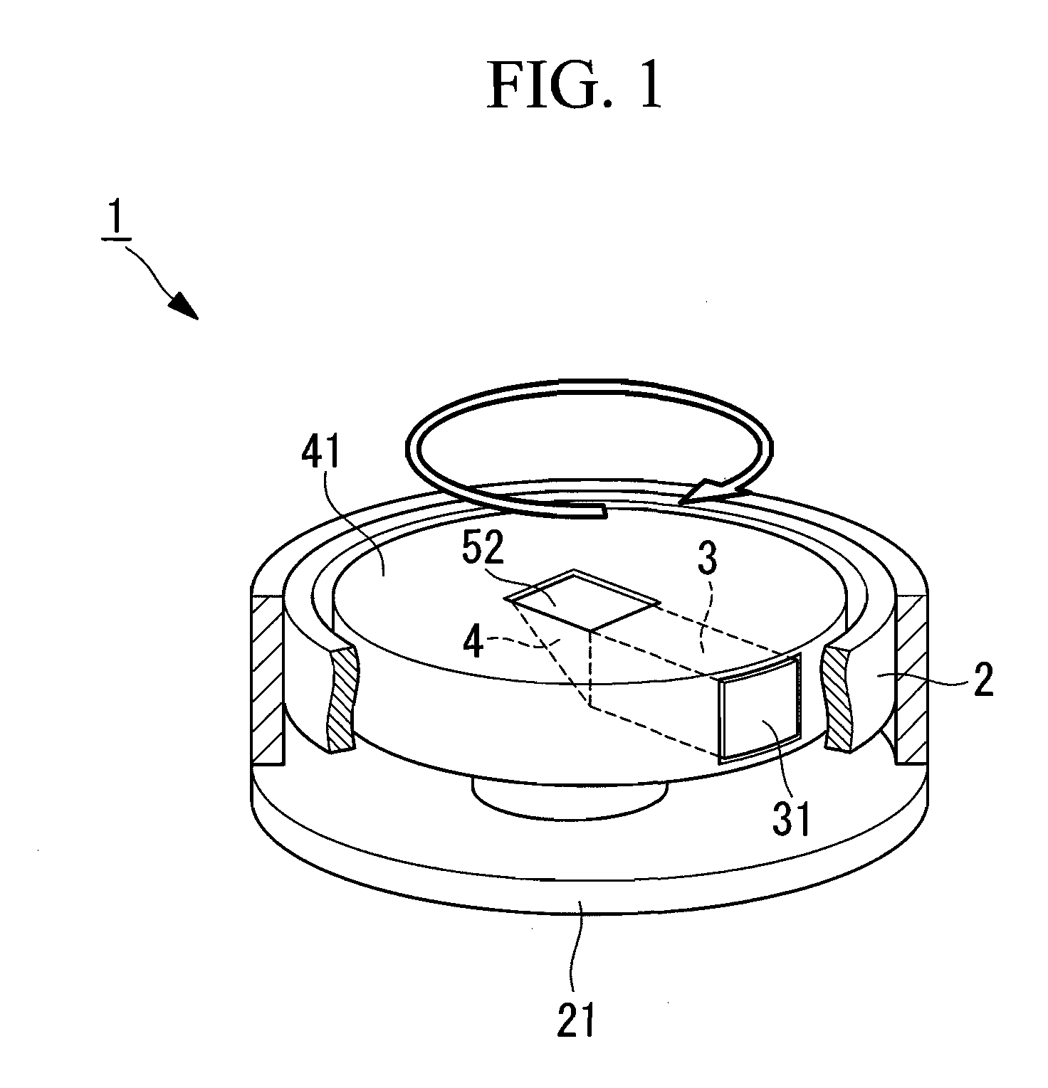
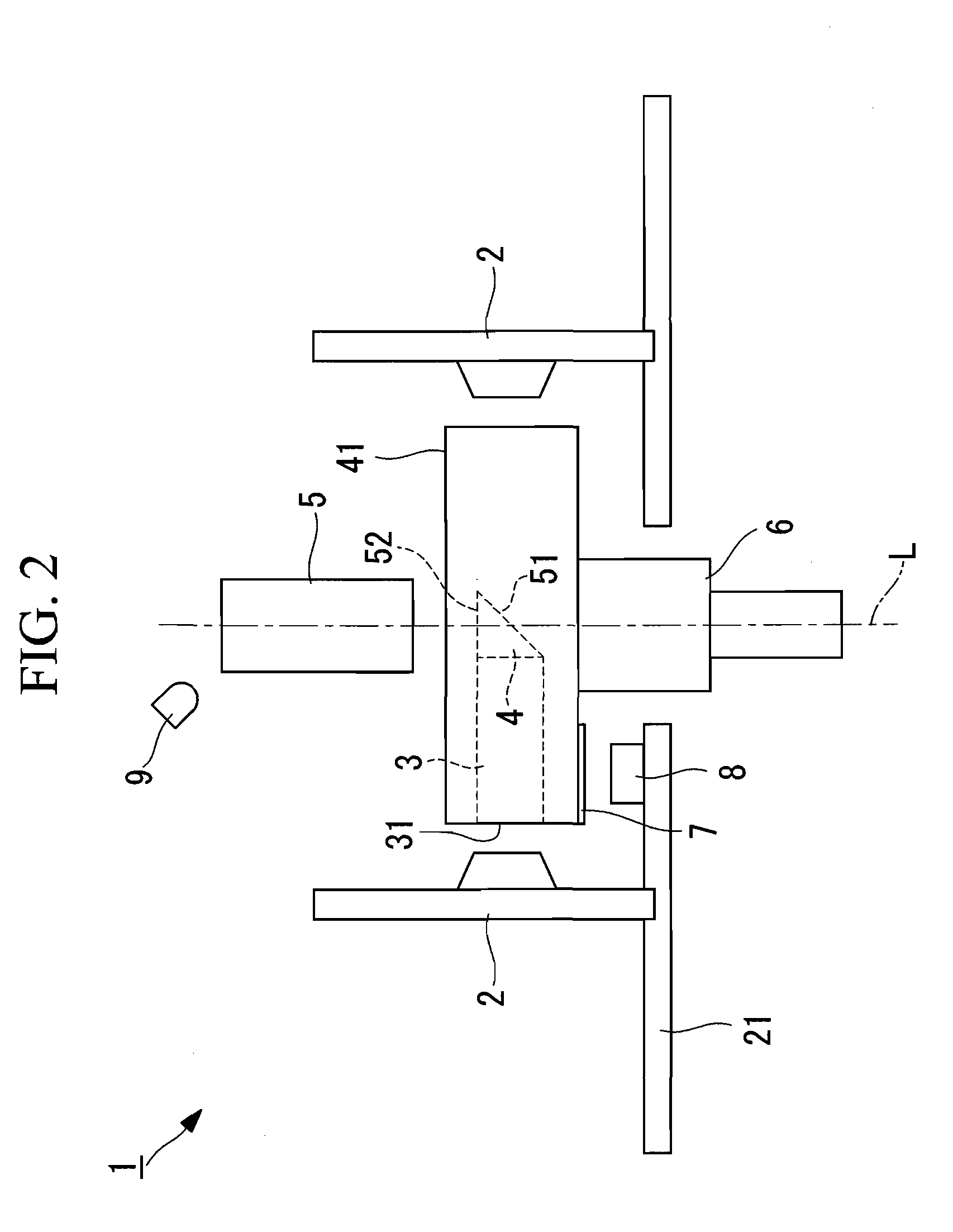
[0049]FIG. 1 is a schematic diagram for explaining, in outline, a light source apparatus of this embodiment. FIG. 2 is a sectional view for explaining the configuration of the light source apparatus of FIG. 1.

[0050]The light source apparatus 1 emits illumination light toward an illuminated region and is used as a light source for medical endoscopes, such as videoscopes, for example.

[0051]As shown in FIGS. 1 and 2, the light source apparatus 1 is provided with a plurality of LEDs (light source devices) 2 that emit illumination light; a light-guide rod (light-guide portion) 3, a reflecting prism (light-guide portion) 4, and a light guide 5 that guide the emitted illumination light to the illuminated region; a motor 6 that rotationally drives the light-guide rod 3 and the reflecting prism 4; a reflecting seal 7 and a rotation detection sensor 8 that detect the rotation phase of the ...

second embodiment

[0155]Next, a second embodiment of the present invention will be described with reference to FIG. 5.

[0156]The basic configuration of the light source apparatus of this embodiment is the same as the first embodiment, but the emission control method of the illumination light differs from that in the first embodiment. Therefore, in this embodiment, only the emission control method of the illumination light will be described using FIG. 5, and a description of other structural elements and so forth will be omitted.

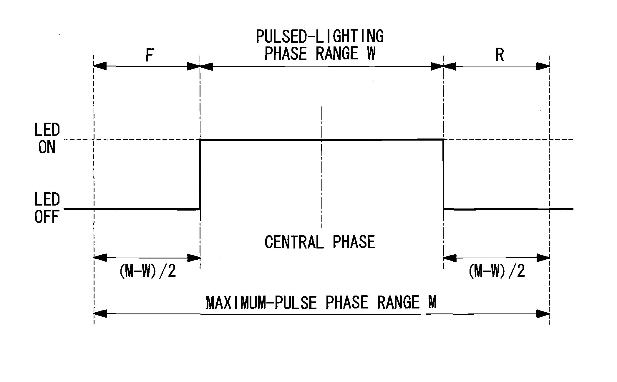
[0157]FIG. 5 is a graph for explaining the emission control of the illumination light when control of the light level of the illumination light is performed by the light source apparatus in this embodiment. In FIG. 5, the horizontal axis indicates the rotation phase of the light-guide rod and the vertical axis indicates the light level of the illumination light emitted.

[0158]The configuration of the light source apparatus 1 and the emission path of the illumination light in thi...


PUM


Abstract

The light source apparatus is provided with a plurality of light source device disposed in the form of a ring and that emit illumination light toward the central axis of the ring by being lit in a sequential pulsed fashion; a light-guide portion having a light entrance surface rotatably disposed on the central axis and on which the illumination light emitted from the light source devices is incident, and a reflecting surface that reflects the incident illumination light in the direction along the central axis; and a driving device that controls a pulsed-lighting phase range. The driving device controls the pulsed-lighting phase range (W) such that, when the pulsed-lighting phase range (W) is shorter than a maximum-pulse phase range (M), a preceding light-out phase range (F) and a succeeding light-out phase range (R) are provided before and after the pulsed-lighting phase range (W) in the maximum-pulse phase range (M).

Description

CROSS REFERENCE TO RELATED APPLICATIONS[0001]This is a continuation of International Application PCT / JP2008 / 072136, with an international filing date of Dec. 5, 2008, which is hereby incorporated by reference herein in its entirety. This application claims the benefit of Japanese Patent Application No. 2008-012488, the content of which is incorporated herein by reference.1. FIELD OF THE INVENTION[0002]The present invention relates to light source apparatuses and, more particularly, to a light source apparatus that guides light emitted from a plurality of light-emitting devices, which emit pulsed light, to an illumination region.2. DESCRIPTION OF RELATED ART[0003]In the related art, with regard to a light source apparatus utilizing light-emitting devices such as LEDs (Light Emitting Diodes) and so forth, there is a known method in which a plurality of light-emitting devices are lit in a sequential pulsed fashion in order to increase the light level of the emitted light. By emitting t...

Claims


Application Information

Patent Timeline
Patent Type & Authority Applications(United States)
IPC IPC(8): H05B41/24
CPCA61B1/0669A61B1/0655
Inventor IKEDA, YOSHINORI
Owner OLYMPUS CORP
Why Eureka
Try Eureka