Controller of power converter

a power converter and control panel technology, applied in the direction of dynamo-electric converter control, motor/generator/converter stopper, instruments, etc., can solve the problems of increasing the switching loss of the inverter, increasing the electromagnetic noise, increasing the switching loss of the semiconductor switching element, etc., to achieve the enhancement of current-control response, the effect of stably changing the carrier frequency and suppressing the loss of the inverter

Inactive Publication Date: 2010-11-04
MITSUBISHI ELECTRIC CORP
View PDF4 Cites 20 Cited by
  • Summary
  • Abstract
  • Description
  • Claims
  • Application Information

AI Technical Summary

Benefits of technology

[0012]According to the controller of a power converter of the present invention, the carrier-frequency setting unit that sets a carrier frequency command used for pulse width modulation of an inverter includes the first two-dimensional map having mapped thereon information of a carrier frequency corresponding to a current command expressed in one of orthogonal axes and a change rate of the current command expressed in the other of the orthogonal axes. The carrier-frequency setting unit outputs to the switching pattern calculator, information of carrier frequency on the first two-dimensional map corresponding to an input current command and a change rate of the input current command. The switching pattern calculator calculates a switching pattern command to perform pulse width modulation based on a voltage command and a carrier frequency command output from the carrier-command setting unit, and outputs the switching pattern to the inverter. Therefore, the controller may stably change the carrier frequency, and may achieve both a current-control response enhancement and loss suppression of an inverter in an improved manner.

Problems solved by technology

On the other hand, when the carrier frequency is set at a high level, there is a problem such that a switching loss of a semiconductor switching element increases, and thus electromagnetic noise also increases.
Meanwhile, when a current control is continued by keeping a high carrier frequency, a switching loss of the inverter increases.

Method used


Image

  • Controller of power converter
  • Controller of power converter
  • Controller of power converter

Examples


first embodiment

(Configuration of Controller)

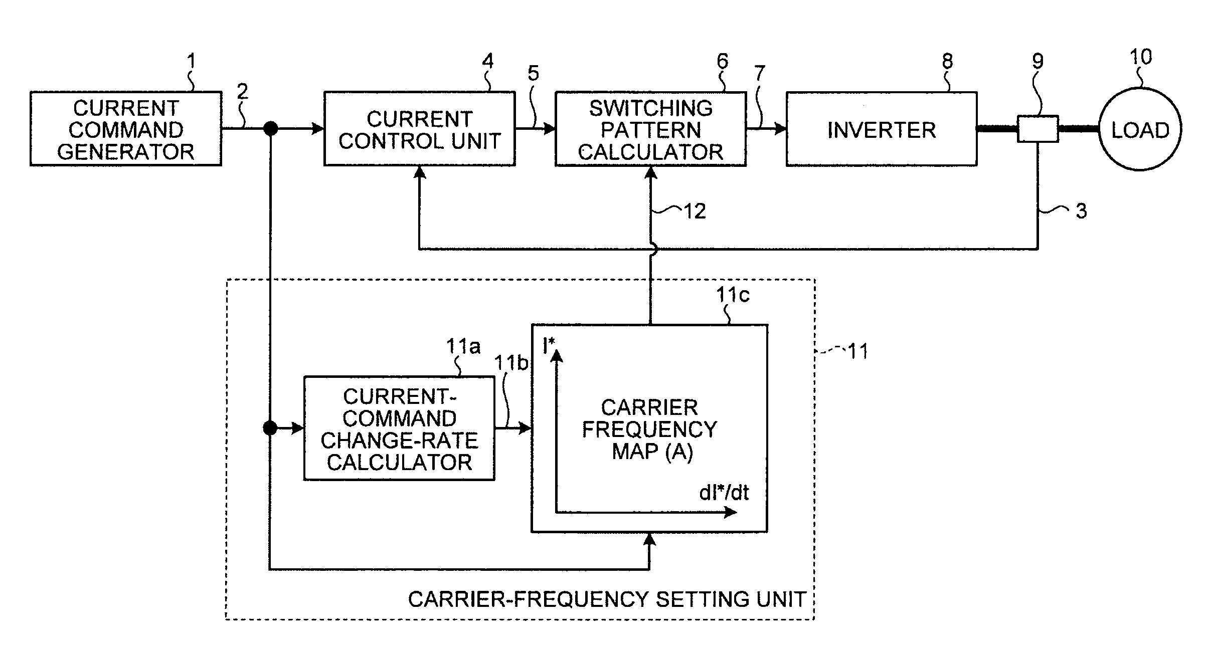
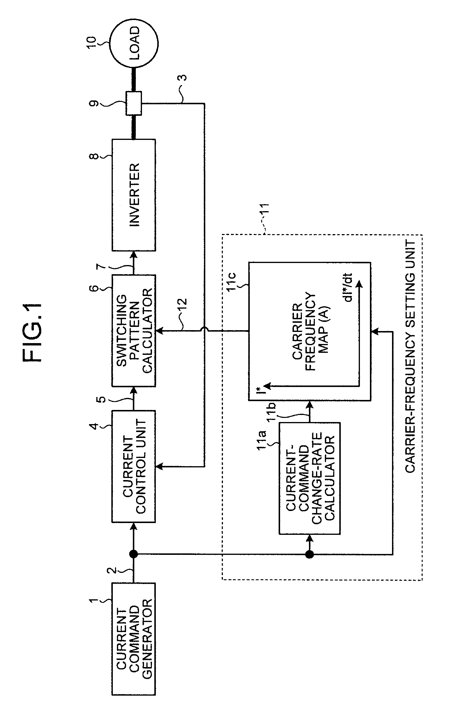
[0062]A configuration of a controller of a power converter according to a first embodiment, that is, the configuration of the controller according to the first embodiment to control the power converter, is explained first. FIG. 1 depicts the configuration of the controller of a power converter according to the first embodiment of the present invention. An inverter, a load connected to the inverter, and a current detector are also illustrated in FIG. 1 for explanation.

[0063]In FIG. 1, the controller according to the present embodiment includes a current command generator 1, a current control unit 4 and a carrier-frequency setting unit 11 to which an output signal of the current command generator 1 is input, and a switching pattern calculator 6 to which an output signal of the current control unit 4 and an output signal of the carrier-frequency setting unit 11 are input. The carrier-frequency setting unit 11 includes a current-command change-rate calculato...

second embodiment

[0082]FIG. 6 depicts a configuration of a controller of a power converter according to a second embodiment of the present invention. Particularly in the present embodiment, an alternate current load such as an alternate current motor and the like is assumed as the load 10, to explain an effect of the present embodiment in more detail. Because the load 10 is an alternate current load, in the present embodiment, coordinate converting units 13 and 15 are further provided in addition to the configuration of the first embodiment shown in FIG. 1. The second embodiment is also different from the first embodiment in that a phase / frequency generator 17 is provided and that a carrier frequency map 11d is provided in the carrier-frequency setting unit 11. Other constituent elements of the second embodiment are identical or equivalent to those illustrated in FIG. 1, and these elements are denoted by like reference letters or numerals.

[0083]The detection current signal 3 is converted into a dete...

third embodiment

[0091]FIG. 7 depicts a configuration of a controller of a power converter according to a third embodiment of the present invention. In the present embodiment, a carrier frequency is decreased while keeping a response characteristic of a current control system at a predetermined value, thereby reducing a switching loss of an inverter.

[0092]In the present embodiment, in addition to the configuration of the first embodiment illustrated in FIG. 1, a current-control-response setting unit 20 is provided, and a carrier frequency map 11f and a current-control-response-command correction-signal setting unit 11g are provided within the carrier-frequency setting unit 11. Other constituent elements of the third embodiment are identical or equivalent to those illustrated in FIG. 1, and these elements are denoted by the same reference letters or numerals as in FIG. 1.

[0093]The current-control-response setting unit 20 sets and outputs an appropriate current-control response command 21 correspondin...


PUM


Abstract

A controller that controls a switching element of an inverter using pulse width modulation is applied to a power converter including an inverter, to realize a stable change of a carrier frequency, current control responsiveness, and inverter loss suppression. The controller includes a carrier-frequency setting unit that sets a carrier frequency command used for pulse width modulation of an inverter corresponding to a current command and a current-command change rate. The carrier-frequency setting unit includes a carrier frequency map having mapped thereon information of a carrier frequency corresponding to a current command expressed in a vertical axis and a current-command change rate expressed in a lateral axis, and outputs information of a carrier frequency on the carrier frequency map corresponding to the input current command and the input current-command change rate to a switching pattern calculator.

Description

TECHNICAL FIELD[0001]The present invention relates to a controller of a power converter that is applied to a power converter including an inverter constituted by plural semiconductor switching elements and controls a switching element of the inverter using pulse width modulation (hereinafter, “PWM”).BACKGROUND ART[0002]With regard to power converters, there is a carrier comparison method as one of representative methods of calculating a switching pattern to PWM control a semiconductor switching element constituting an inverter. According to the carrier comparison method, a voltage command to the inverter and a size of a carrier wave are compared, thereby determining an on / off pattern to perform a switch control. A triangular wave is often used as the carrier wave.[0003]In a power converter using the carrier comparison method, a frequency of a carrier wave (hereinafter, “carrier frequency”) is an important parameter to determine a characteristic of the power converter. For example, w...

Claims


Application Information

Patent Timeline
Patent Type & Authority Applications(United States)
IPC IPC(8): G05F1/10H02M1/00
CPCH02M1/0845H02P27/08H02M2001/0012H02M7/537H02M1/0012
Inventor FURUTANI, SHINICHISATAKE, AKIRASAWAKI, JUN
Owner MITSUBISHI ELECTRIC CORP
Why Eureka
Try Eureka