Liquid Ejection Apparatus And Head Maintenance Method

a technology of liquid ejection and maintenance method, which is applied in the direction of printing, inking apparatus, other printing apparatus, etc., can solve the problems of ejection failure or deviation of ejection direction, difficult to remove aggregated material (solidified material) produced inside the nozzle, and abnormal ejection, so as to prevent the dispersion of pressure applied and improve maintenance efficiency

Inactive Publication Date: 2010-11-04
FUJIFILM CORP
View PDF1 Cites 12 Cited by
  • Summary
  • Abstract
  • Description
  • Claims
  • Application Information

AI Technical Summary

Benefits of technology

[0015]According to the present invention, since the nozzles which are capped simultaneously by the capping device are limited to nozzles which receive supply of liquid fr...

Problems solved by technology

It is known that in an inkjet recording apparatus which forms an image or a prescribed pattern on a recording medium by ejecting a functional material, such as ink, by means of an inkjet head, if blocking of foreign matter or infiltration of air bubbles occurs inside the nozzles of the inkjet head, then ejection abnormalities such as ejection failures or deviation of the ejection direction, and the like, arise.
In particular, if a liquid which generates an aggregated material upon drying, such as an ink containing a high-boiling-point organic solvent having a low SP value, is used, then it is difficult to remove the aggregated material (solidified material) produced inside the nozzles and there is an increased possibility of ejection abnormalities occurring due to the aggregated material produced inside the nozzles.
In particular, there has recently been...

Method used


Image

  • Liquid Ejection Apparatus And Head Maintenance Method
  • Liquid Ejection Apparatus And Head Maintenance Method
  • Liquid Ejection Apparatus And Head Maintenance Method

Examples


first application example

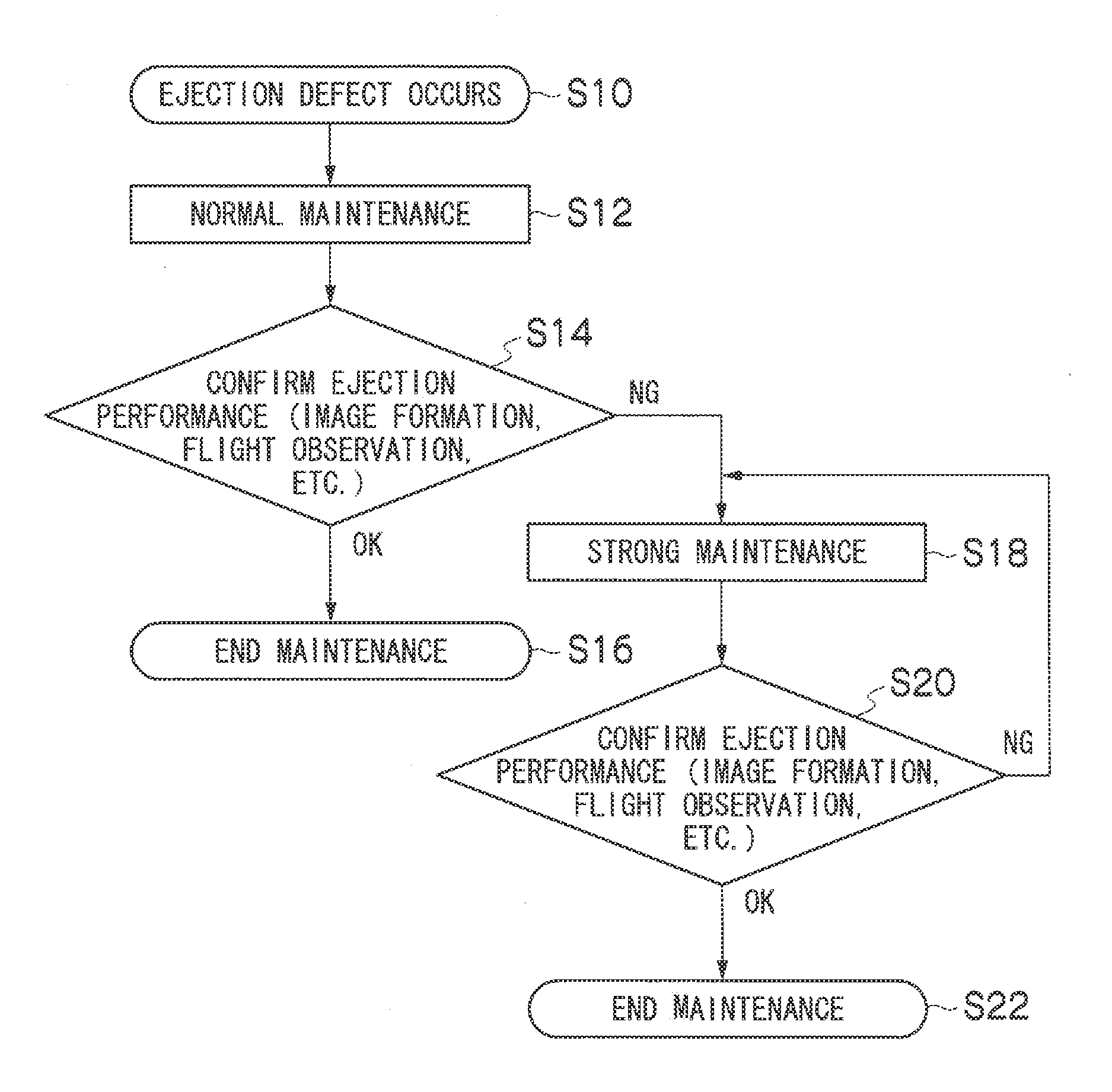
[0150]FIG. 14 is a block diagram showing the approximate composition of a maintenance processing unit relating to an application example of the present invention.

[0151]In order to carry out maintenance processing of the whole of the head 150 by using the maintenance processing unit 161 described above, it is necessary to carry out processing several times while moving the cap 164, and hence there is a possibility that a long time is needed for the whole process.

[0152]FIG. 14 is a block diagram showing a composition for resolving the problem described above. The maintenance processing unit 261 shown in FIG. 14 has a structure in which a single cap structure body 264 is formed by aligning together n caps 164 (164-1 to 164-n) in the lengthwise direction of the head 150, in such a manner that the whole of the head 150 can be capped simultaneously.

[0153]Furthermore, switching valves 266-1 to 266-n are provided for the caps 164-1 to 164-n, thereby achieving a composition where it is possi...

second application example

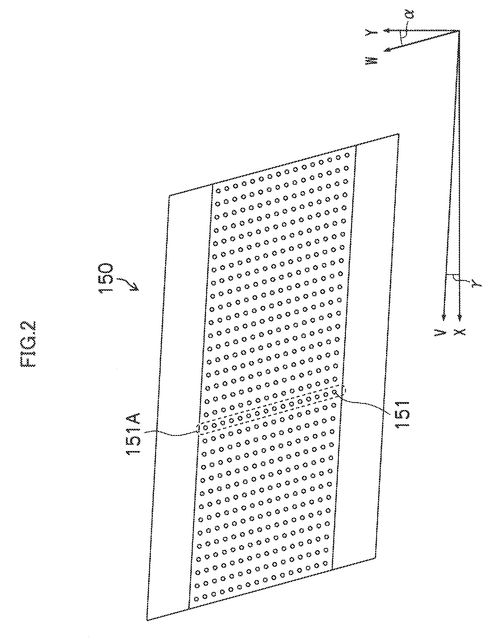
[0156]FIG. 15 is a plan diagram showing a full line type head 150′ composed by joining together a plurality of head modules 150-1 to 150-n (150-i, where i is an integer between 1 and n), as viewed from the nozzle surface 150A side, and FIG. 16 is a partial enlarged diagram of FIG. 15.

[0157]In this example, capping is performed respectively for each head module 150-i in a head 150′ composed by a plurality of head modules 150-i joined together, and furthermore, the nozzle arrangement region in each head module 150-i is divided equally (into three sections), which respectively form capping regions 300-1 to 300-3.

[0158]More specifically, the cap described in the present example has a structure comprising three caps joined together, each cap corresponding to a capping region 300-1 (300-2, 300-3), and is composed in such a manner that any one of the three caps can be connected selectively to a pump.

[0159]Maintenance processing is carried out successively in respect of the capping regions ...


PUM


Abstract

A liquid ejection apparatus includes: an inkjet head including a plurality of nozzles which eject liquid containing a water-soluble high-boiling-point organic solvent having an SP value of 30 or lower at a concentration of 10 weight percent or higher and 25 weight percent or lower, a plurality of liquid chambers connected to the plurality of nozzles respectively, and a plurality of supply flow channels to any of which each of the plurality of nozzles is connected and which supply the liquid to the plurality of nozzles via the plurality of liquid chambers; a capping device configured to simultaneously cap the nozzles connected to the same supply flow channel, from a liquid ejection surface side of the inkjet head; a pressure application device which applies pressure to the liquid inside the nozzles via the capping device; and a pressure control device which controls the pressure application device so as to repeat pressurization and depressurization with respect to the liquid inside the nozzles.

Description

BACKGROUND OF THE INVENTION[0001]1. Field of the Invention[0002]The present invention relates to a liquid ejection apparatus and a head maintenance method, and more particularly to maintenance technology for a liquid ejection surface of an inkjet head.[0003]2. Description of the Related Art[0004]As a general image recording apparatus, it is suitable to use an inkjet recording apparatus, which forms a desired image on a recording medium by ejecting and depositing colored inks from a plurality of nozzles provided in an inkjet head.[0005]It is known that in an inkjet recording apparatus which forms an image or a prescribed pattern on a recording medium by ejecting a functional material, such as ink, by means of an inkjet head, if blocking of foreign matter or infiltration of air bubbles occurs inside the nozzles of the inkjet head, then ejection abnormalities such as ejection failures or deviation of the ejection direction, and the like, arise. In particular, if a liquid which generate...

Claims


Application Information

Patent Timeline
IPC IPC(8): B41J29/38B41J2/165B41J2/145
CPCB41J2/14233B41J2/16526B41J2/16532B41J2/16552B41J2202/21B41J2/17596B41J29/38B41J2002/14459B41J2202/20B41J2/16585
Inventor NISHIKAWA, BAKU
Owner FUJIFILM CORP
Why Eureka
Try Eureka