Power tool having a work field lighting system

a technology of work field lighting and power tools, which is applied in the direction of lighting, instruments, lighting and heating apparatus, etc., can solve the problems of requiring additional space and easy damage of light sources, and achieve the effect of space-saving and more precise work and positioning of power tools

Active Publication Date: 2010-11-04
ROBERT BOSCH GMBH
View PDF12 Cites 19 Cited by
  • Summary
  • Abstract
  • Description
  • Claims
  • Application Information

AI Technical Summary

Benefits of technology

[0008]Advantageously, the lighting means, or its primary beam of light, can be disposed at any angle to the tool holder axis. Because the transparent element is integrated with the housing, and the lighting means can be disposed separately from it, the structural height or length is not necessarily adversely affected. The housing itself can be embodied in one piece or in multiple parts. The disposition of the lighting means in relation to the transparent element can be selected independently of a necessary beam of light direction for illuminating the work field after the beam leaves the transparent element. This allows great freedom of design. The structural length of the lighting unit comprising the lighting means and the transparent element is slight. The structural height can be designed arbitrarily. Advantageously, the result is great flexibility in disposing the lighting means in relation to the tool holder.
[0019]The lighting means can favorably be activated when the switch actuation element is pressed, before a motor can be switched on by the switch actuation element. The work field lighting system can then already be active and illuminate the work field before the motor begins to rotate. This makes more-precise work and positioning of the power tool possible.

Problems solved by technology

The switch actuation element therefore has a greater spacing from the gearbox, and the lighting means can easily be damaged.
With conventional cabling, the cables must typically be extended around a movable switch for changing the direction of rotation, and this requires additional space.

Method used


Image

  • Power tool having a work field lighting system
  • Power tool having a work field lighting system
  • Power tool having a work field lighting system

Examples


Embodiment Construction

[0028]In the drawings, identical or identically functioning elements are identified by the same reference numerals.

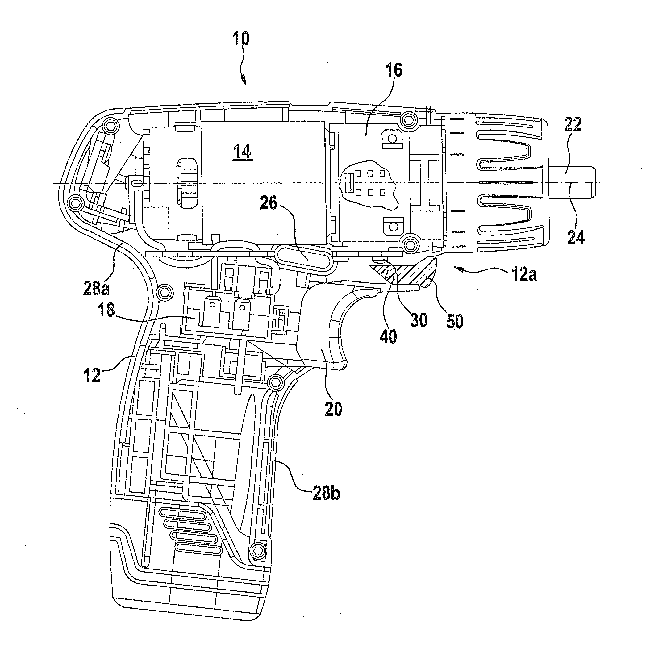
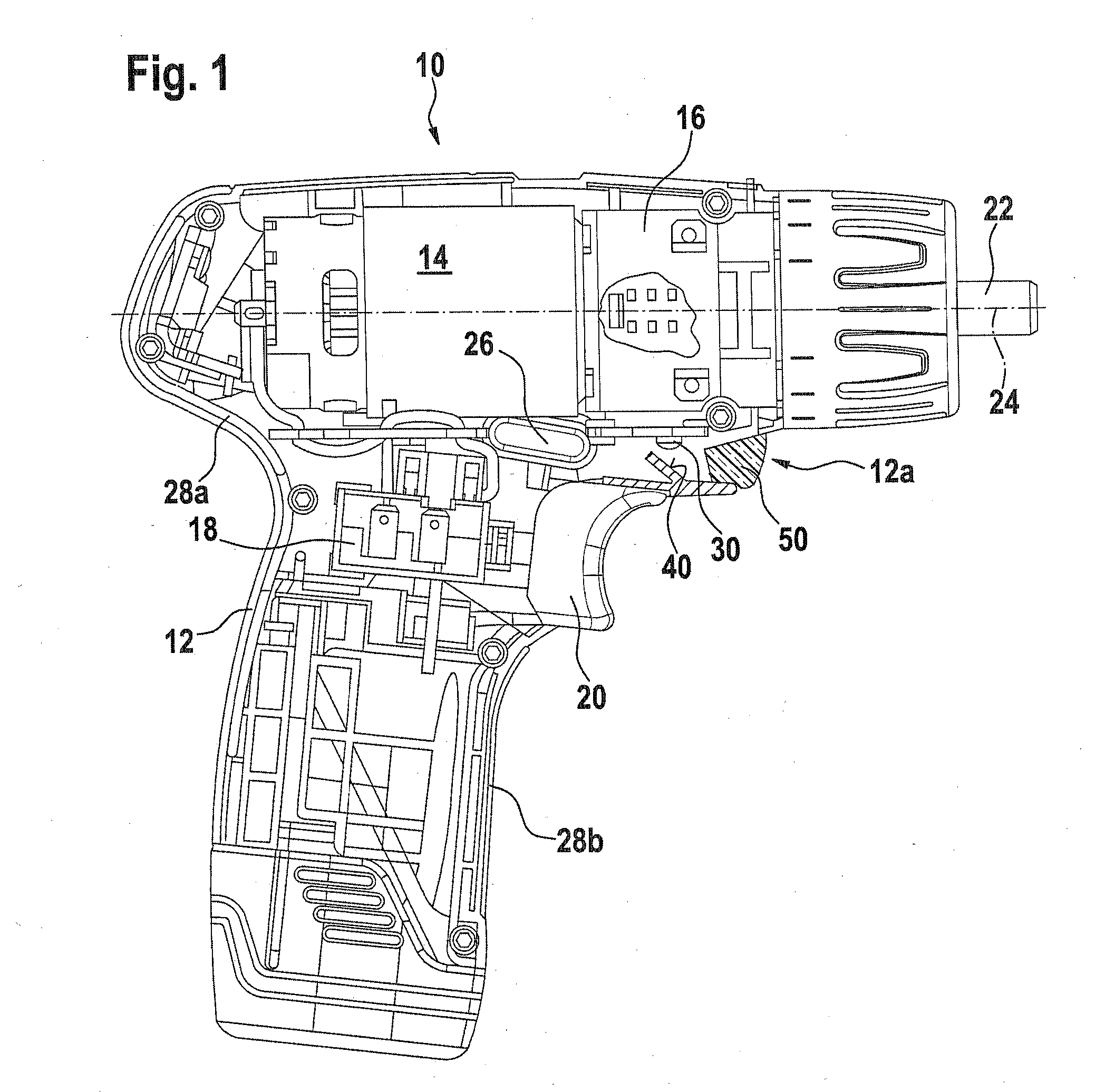
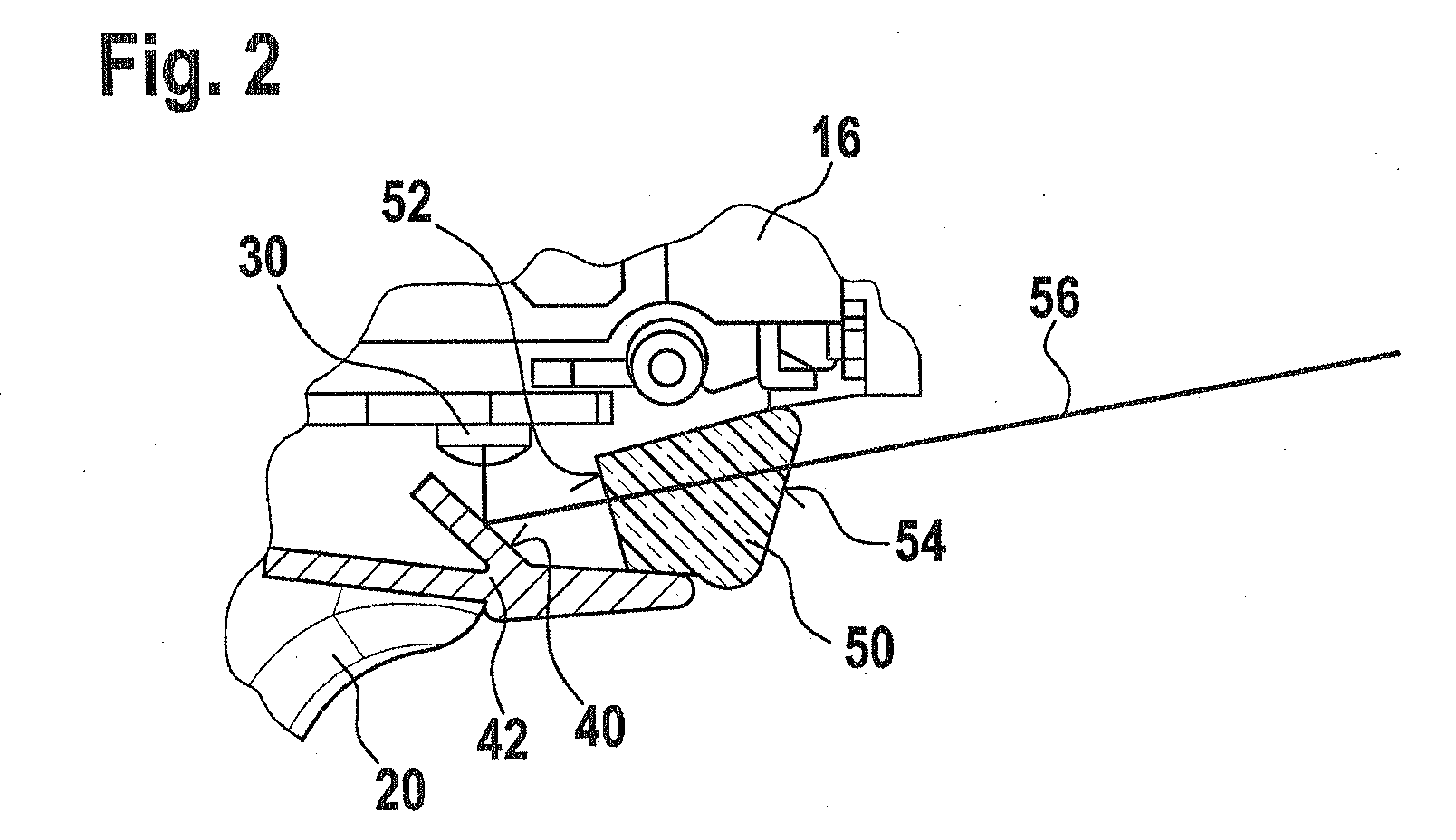
[0029]For explanation of the invention, FIGS. 1 and 2 show a section through a power tool 10 in a first preferred embodiment. FIG. 2 shows a detail of that embodiment.

[0030]The power tool 10, embodied for instance as a cordless electric power tool, having a housing identified overall by reference numeral 12 includes a motor 14 in a motor housing 28a, with a gear 16, which is connected in the direction of a tool holder axis 24 and is disposed in a gearbox not identified by reference numeral, and adjoining it, a tool holder 22 for a tool insert, not shown. A switch 26 for changing the direction of rotation is disposed underneath the motor 14 and adjacent to it. The tool insert can be driven in rotary and / or percussive fashion. Underneath the motor 14 is a switch 18 for switching the motor 14 on and off; it can be actuated by a user of the power tool 10 via a switch actuat...


PUM

PropertyMeasurementUnit
transparentaaaaaaaaaa
total reflectionaaaaaaaaaa
angleaaaaaaaaaa

Abstract

The invention relates to a machine tool having working field illumination disposed in a housing, having an illumination mechanism and a transparent element which allows the light from the illumination mechanism to be led out toward the working field. A light beam can be deflected between the illumination mechanism and the transparent element. According to the invention, the transparent element forms a region of the housing.

Description

PRIOR ART[0001]The invention relates to a power tool having a work field lighting system, as generically defined by the preamble to claim 1.[0002]Handheld electric power tools, such as plug-in and / or cordless screwdrivers, rotary drills, impact screwdrivers or impact power drills have a gear, a motor, a switch with a switch actuation element accessible on the housing, and a motor housing. It is known to equip such tools with a work field lighting system, so that work can be done even under unfavorable light conditions.[0003]From German Utility Model 297 19 020 U1, an electric power tool is known in which a lighting means is disposed underneath the gear, above the switch actuation element. Typically, the lighting means must be disposed at an angle to the tool holder axis, so that it can also illuminate the end of short tool bits, such as short screwdriver bits. Although the structural length of the lighting unit is advantageously short in the tool bit axis direction, nevertheless an ...

Claims


Application Information

Patent Timeline
Patent Type & Authority Applications(United States)
IPC IPC(8): B25B23/18
CPCB25B21/00B25B23/18Y10T408/21F21V33/0084B25F5/021
Inventor HECHT, JOACHIMBRENNENSTUHL, JENSROEHM, HEIKO
Owner ROBERT BOSCH GMBH
Why Eureka
Try Eureka