Check patentability & draft patents in minutes with Patsnap Eureka AI!

Fixed eyebolt assembly and inventory thereof

a technology of fixed eyebolts and assembly, applied in the field of eyebolts, can solve the problems of safety hazards, special tools not available or used to accomplish such removal and reinstallation, and the configuration of fixed eyebolts cannot accommodate this situation, so as to achieve reliable access and strengthen the skirt

Inactive Publication Date: 2010-11-04
MJT HLDG
View PDF4 Cites 2 Cited by
  • Summary
  • Abstract
  • Description
  • Claims
  • Application Information

AI Technical Summary

Benefits of technology

This design reduces inventory costs by allowing a single eyebolt body to be used with various mounting components, minimizing damage and enabling safe, direction-independent load support, thus enhancing safety and reducing operational expenses.

Problems solved by technology

Typically, special tools to accomplish such removal and reinstallation are not available or are not used.
In general, fixed eyebolts are not configured to accommodate this situation.
Inadequate tightening of an eyebolt to a substrate may result in a safety hazard.
Repeated or improper removal and reinstallation often damages the threads or other mounting elements by which fixed eyebolts are secured to substrates.
Damaged eyebolts must be refurbished or replaced.
When an eyebolt with an integral mounting component becomes damaged, the entire eyebolt is often discarded.
The body of a typical eyebolt is the most expensive part of the assembly, and comprises the majority of the high grade alloy that is used in the device.
The equipment that is required to process high strength alloys requires a considerable capital investment, and operational costs are significant.
Even if the installation instructions are known, and they are followed, unexpected shifts in the direction of the applied load may create a safety hazard.
The necessity to orient the eye in a particular direction to accommodate a load may result in less than optimum tightening of the eyebolt, thus creating a safety hazard.

Method used


Image

  • Fixed eyebolt assembly and inventory thereof
  • Fixed eyebolt assembly and inventory thereof
  • Fixed eyebolt assembly and inventory thereof

Examples


Embodiment Construction

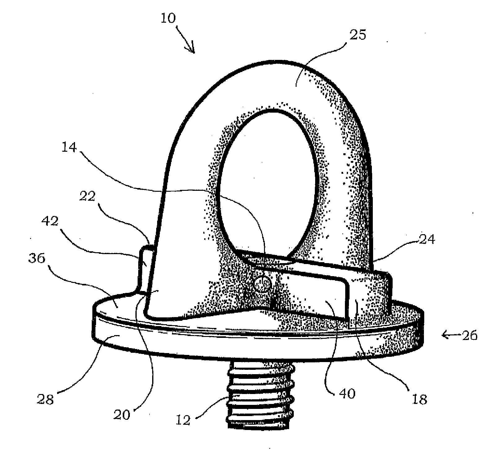
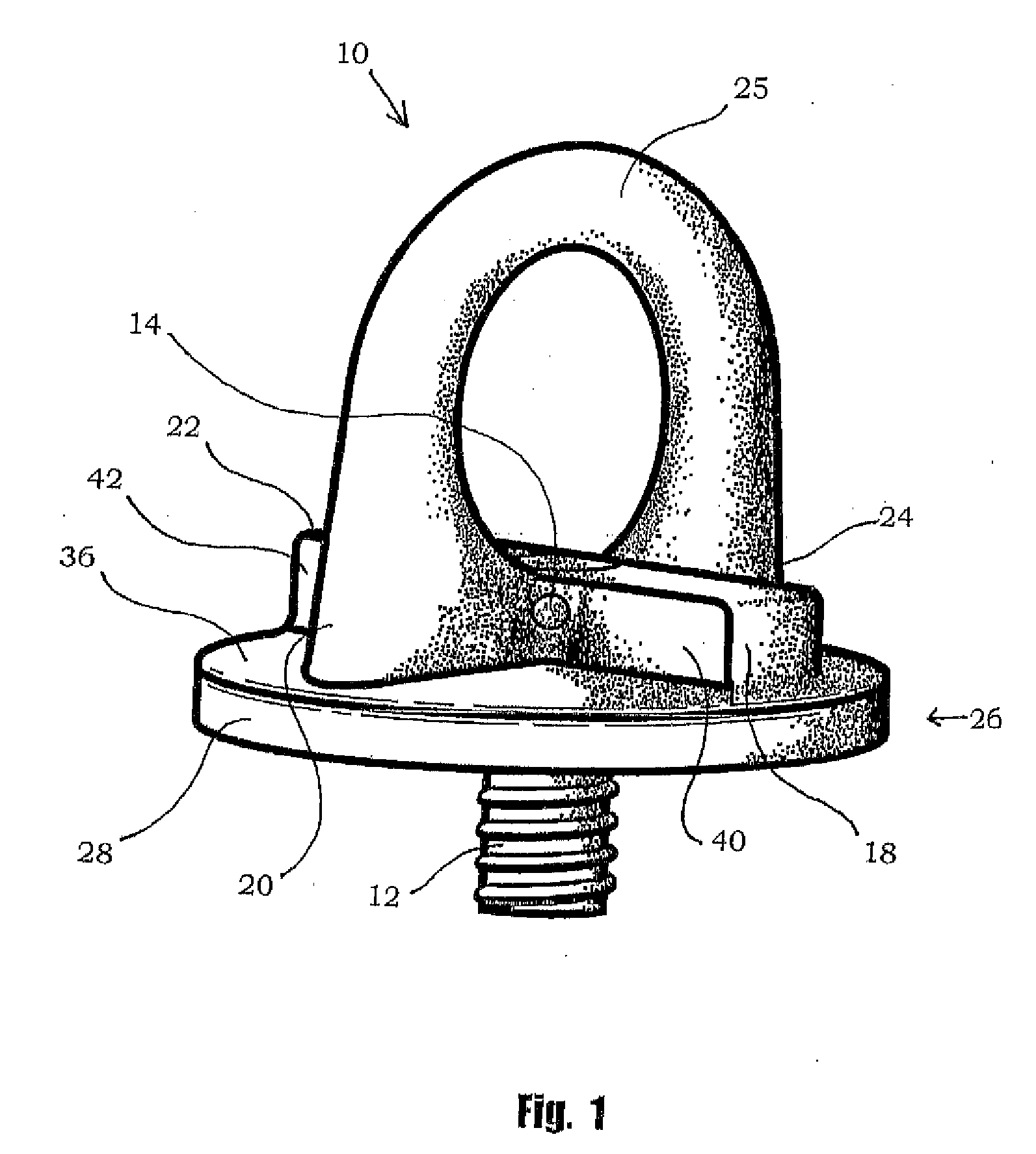
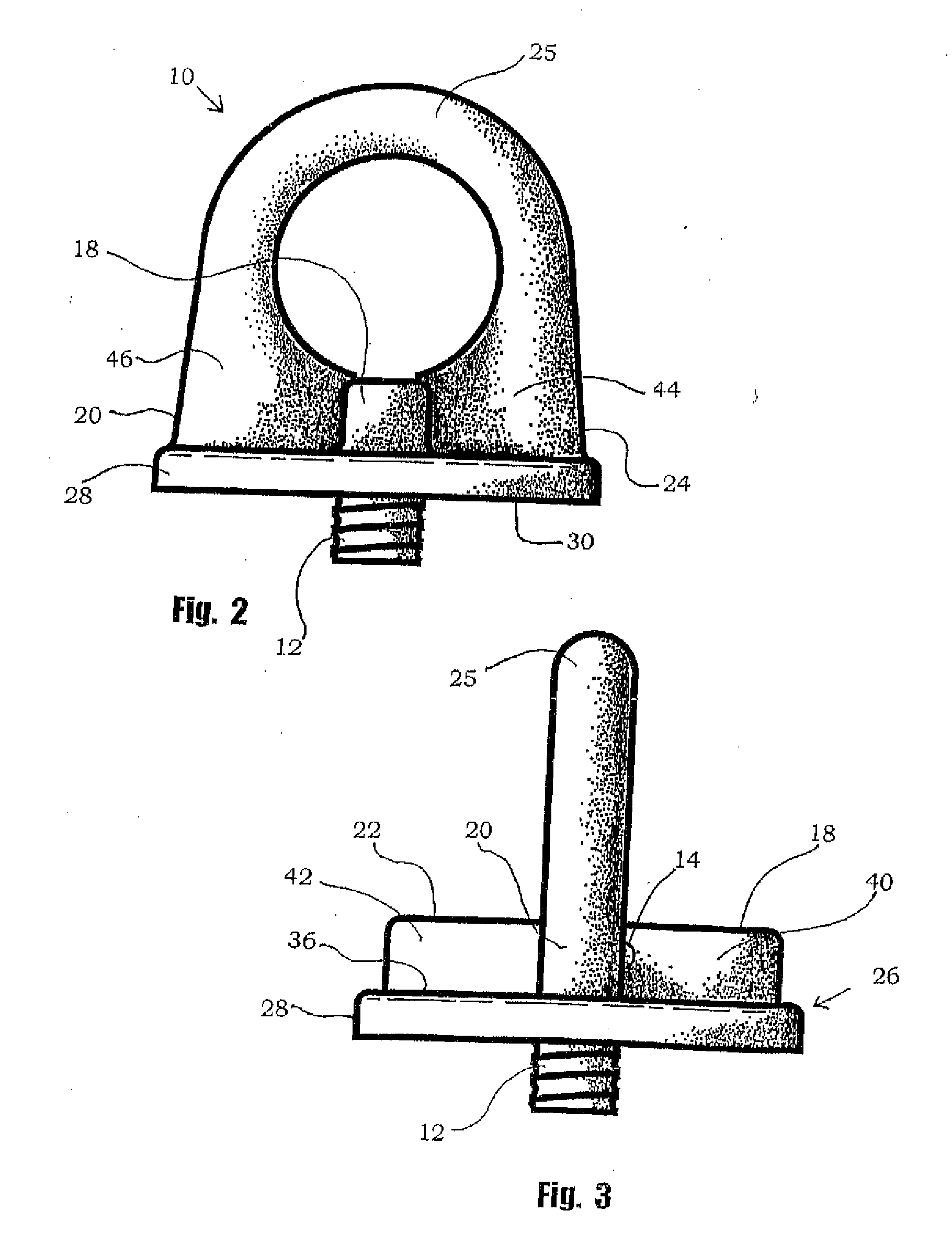
[0028]Referring now to the drawings wherein like reference numerals designate identical or corresponding parts throughout the several views, there is illustrated generally at 10 a fixed eyebolt assembly composed of an eyebolt body and a mounting stud 12. Preferably, mounting stud 12 is separable from the eyebolt body. To this end, if desired, a retainer pin 14 may be provided for retaining insertion in cross-bore 16. Cross-bore 16, when provided, extends through both a mounting component, for example, mounting stud 12, and at least one of the reinforcing elements, for example, the junction of rib members 18 and 20, so that the insertion of retainer pin 14 locks the mounting stud 12 and the eyebolt body together. The combination of a cross-bore and retainer pin can be replaced, as will be understood by those skilled in the art, with other securing elements. For example, the end of the mounting stud 12 can be extended up entirely through the intersection of the reinforcing elements so...


PUM


Abstract

An eyebolt assembly is provided in which a skirt member is reinforced by radially projecting diametrically extending ribs. A fixed lifting eye projects from one side of the skirt, and a mounting stud projects from the opposite side. The mounting stud is double threaded with one thread being adapted to mate with a threaded bore in the body of the eyebolt assembly, and the other thread being matched to a threaded bore in a load. The same eyebolt body can be employed with a plurality of different mounting studs, which simplifies inventorying eyebolt assemblies to meet all of the different threaded bores that may occur in different loads. Only the mounting studs need to be threaded to match the loads. The skirts are provided with striking faces so that they can be tightened and loosened by striking them with a hammer.

Description

RELATED APPLICATIONS[0001]The benefit of U.S. Provisional Application Ser. No. 60 / 365,860, filed Mar. 19, 2002, is claimed.BACKGROUND OF THE INVENTION[0002]1. Field of the Invention[0003]The invention relates in general to eyebolts and, in particular, to fixed eyebolt assemblies, and to eyebolt inventory control methods.[0004]2. Description of the Prior Art[0005]Eyebolts of various configurations have been proposed for various purposes. See, for example, Ake U.S. Des. 275,868; Bethea U.S. Des. 286,979; Palmer U.S. Des. 309,251; Schriever U.S. Des. 360,353; Kraine U.S. Des. 415,951; and Bohli U.S. Pat. No. 3,866,873, which all relate generally to fixed eyebolts with integral washers and separately provided fasteners that mount generally centrally of the eyebolt structure. Mueller U.S. Pat. No. 3,492,033; Motz U.S. Pat. No. 4,408,941; Seidel U.S. Pat. No. 4,699,410; and Pearl U.S. Pat. No. 6,161,883, all relate generally to mounting studs that are threadabiy received in both a substra...

Claims


Application Information

Patent Timeline
Patent Type & Authority Applications(United States)
IPC IPC(8): F16B35/06B66C1/66F16B39/04F16B45/00
CPCB66C1/66F16B39/04F16B45/00Y10T403/32303G06Q10/0875G06Q30/0601G06Q10/087F16B45/002
Inventor ALBA, TONY J.STRANAHAN, PHIL
Owner MJT HLDG
Features
  • R&D
  • Intellectual Property
  • Life Sciences
  • Materials
  • Tech Scout
  • Unparalleled Data Quality
  • Higher Quality Content
  • 60% Fewer Hallucinations
Learn More