Method and Apparatus for Heart Rate Monitoring

a technology of electrocardiogram and heart rate, applied in the field of method and apparatus for electrocardiogram based rate detection, can solve problems such as inability to adapt to variations in relative amplitud

Active Publication Date: 2010-11-04
TEXAS INSTR INC
View PDF1 Cites 21 Cited by
  • Summary
  • Abstract
  • Description
  • Claims
  • Application Information

AI Technical Summary

Problems solved by technology

This method, though straight forward has the disadvantage

Method used


Image

  • Method and Apparatus for Heart Rate Monitoring
  • Method and Apparatus for Heart Rate Monitoring
  • Method and Apparatus for Heart Rate Monitoring

Examples


Embodiment Construction

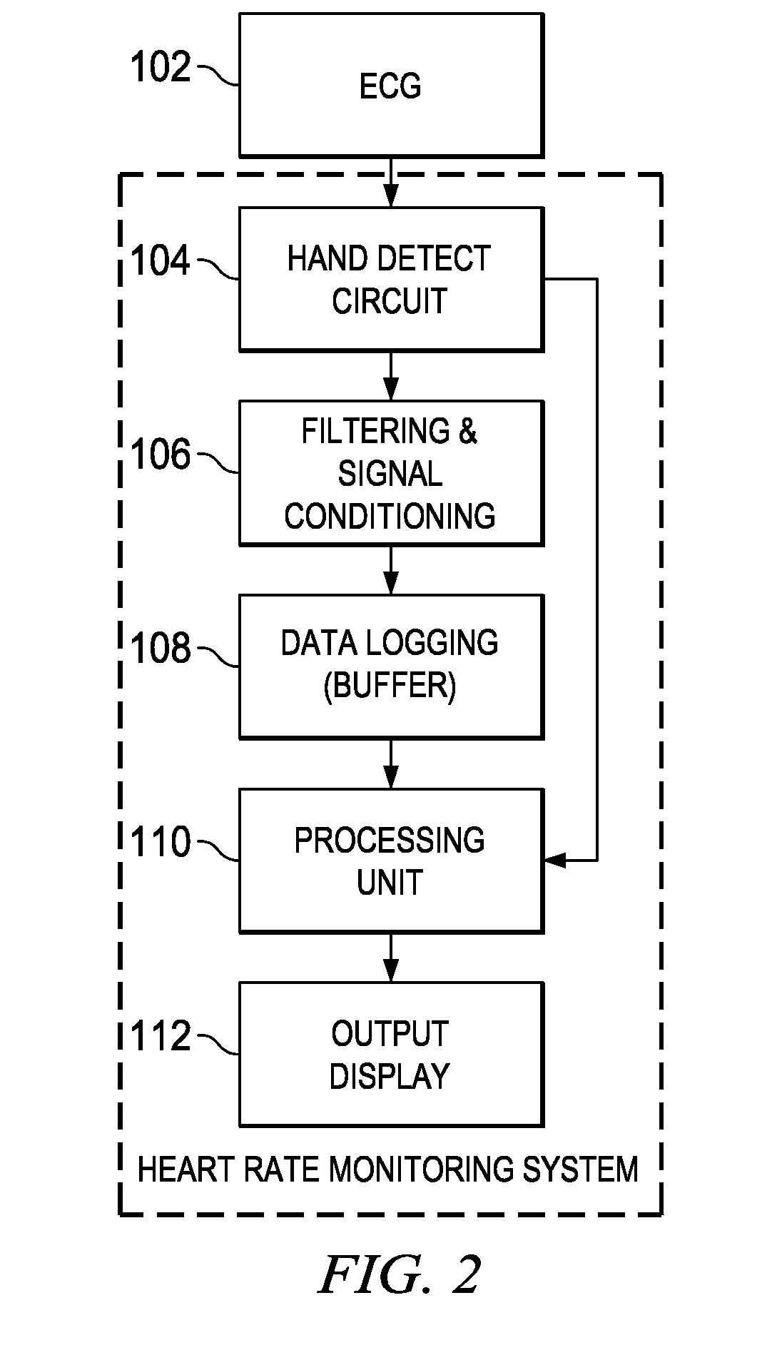
[0010]FIG. 1 is an embodiment depicting a block diagram for a heart rate monitoring system 100. The heart rate monitor system comprises an electrocardiogram (ECG) 102, a Hand detect circuit 104, a filtering signal conditioning unit 106, a data logging buffer 108, a processing unit 110, and an output display 112.

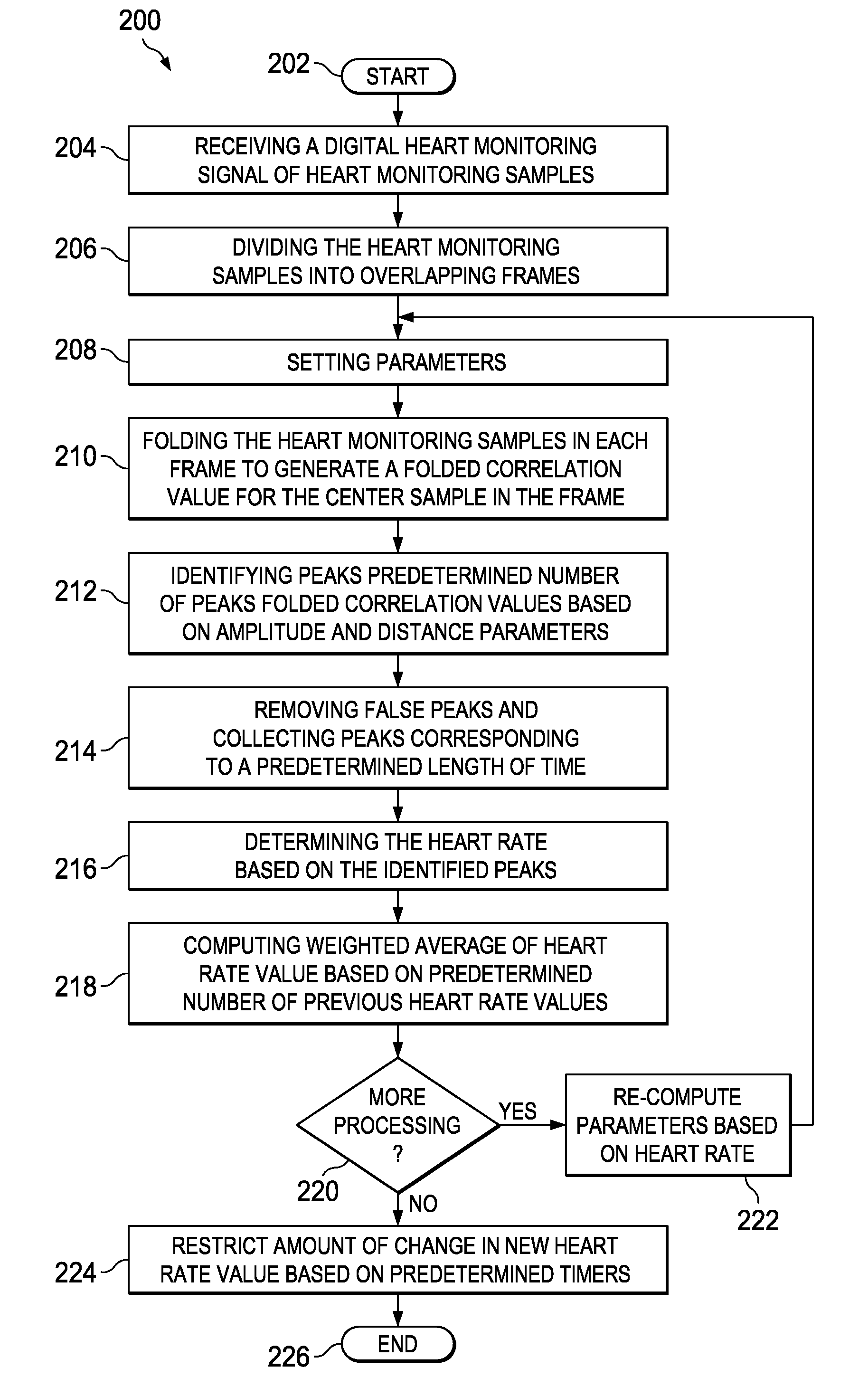
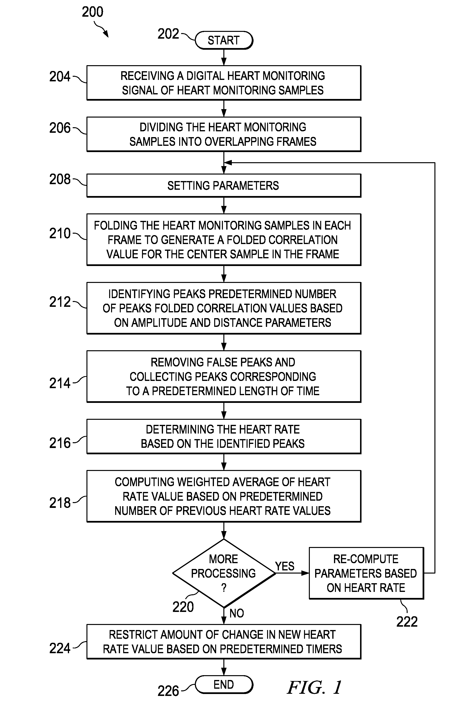
[0011]Herein, the proposed system 100 is a mixed analog and digital solution. The DC offset removal of the acquired signal is accomplished using a single-pole analog high-pass filter, i.e., with a cutoff frequency of 7 Hz. The signal is then passed through a low-pass filter with, i.e., a 27 Hz cut-off frequency to remove out-of-band noise. The analog front-end also provides sufficient gain to the acquired signal. The signal is then processed by a CPU. In one embodiment, a block processing algorithmic approach is utilized, which allows for a more efficient and accurate paradigm for heart rate detection from ECG 102. The approach also allows us to perform back-end signal proces...


PUM


Abstract

A method and apparatus for monitoring heart rate. The method includes receiving a digital heart monitoring signal, determining the integrity of said signal with a “hand detect” signal that confirms electrical connection to the subject, dividing the digital heart monitoring signal into at least one frame, generating a folded correlation value for the center sample in the at least one frame, identify the number of peaks folded correlation values based on amplitude and distance parameters of the digital heart monitoring signal in the at least one frame, removing false peaks and collecting peaks corresponding to a length of time, determining the heart rate based on the identified peaks wherein the identified peaks relate to a minimum distance between valid heart beat peaks based on a heart rate estimate, computing the weighted average of heart rate value based on the number of previous heart rate values.

Description

CROSS-REFERENCE TO RELATED APPLICATIONS[0001]This application claims benefit of U.S. provisional patent application Ser. No. 61 / 174,291, filed Apr. 30, 2009, which is herein incorporated by reference.BACKGROUND OF THE INVENTION[0002]1. Field of the Invention[0003]Embodiments of the present invention generally relate to a method and apparatus for electrocardiogram (ECG) based rate detection. More specifically, the ECG based rate detector functions in real-time, is low complexity and utilizes low-memory.[0004]2. Description of the Related Art[0005]Heart rate detection from electrocardiogram (ECG) signal has been well studied. Some methods proposed previously, detect the QRS complex peaks by high pass filtering and subtraction of a fixed threshold. This method, though straight forward has the disadvantage that it is not robust to variations in relative amplitude. Another technique proposes use of discrete wavelet transform to remove mean variations and other artifacts. The peaks corres...

Claims


Application Information

Patent Timeline
IPC IPC(8): A61B5/0402
CPCA61B5/0245A61B5/7221A61B5/7203A61B5/7246
Inventor DUNBAR, STEVEN T.RAVINDRAN, SOURABH
Owner TEXAS INSTR INC
Why Eureka
Try Eureka