Self loading utility knife

Active Publication Date: 2010-11-11
HAO WEN
View PDF26 Cites 51 Cited by
  • Summary
  • Abstract
  • Description
  • Claims
  • Application Information

AI Technical Summary

Benefits of technology

[0014]It is an additional object of the invention to provide the utility knife as in the previous objects that provides a smooth operation, includes a quick release blade mechanism that is only accessible

Problems solved by technology

However, it is not convenient to replace the blade.
However, the following problems exist.
The structure is complex; when replacing a blade, a user needs to release the lock memb

Method used


Image

  • Self loading utility knife
  • Self loading utility knife
  • Self loading utility knife

Examples


Embodiment Construction

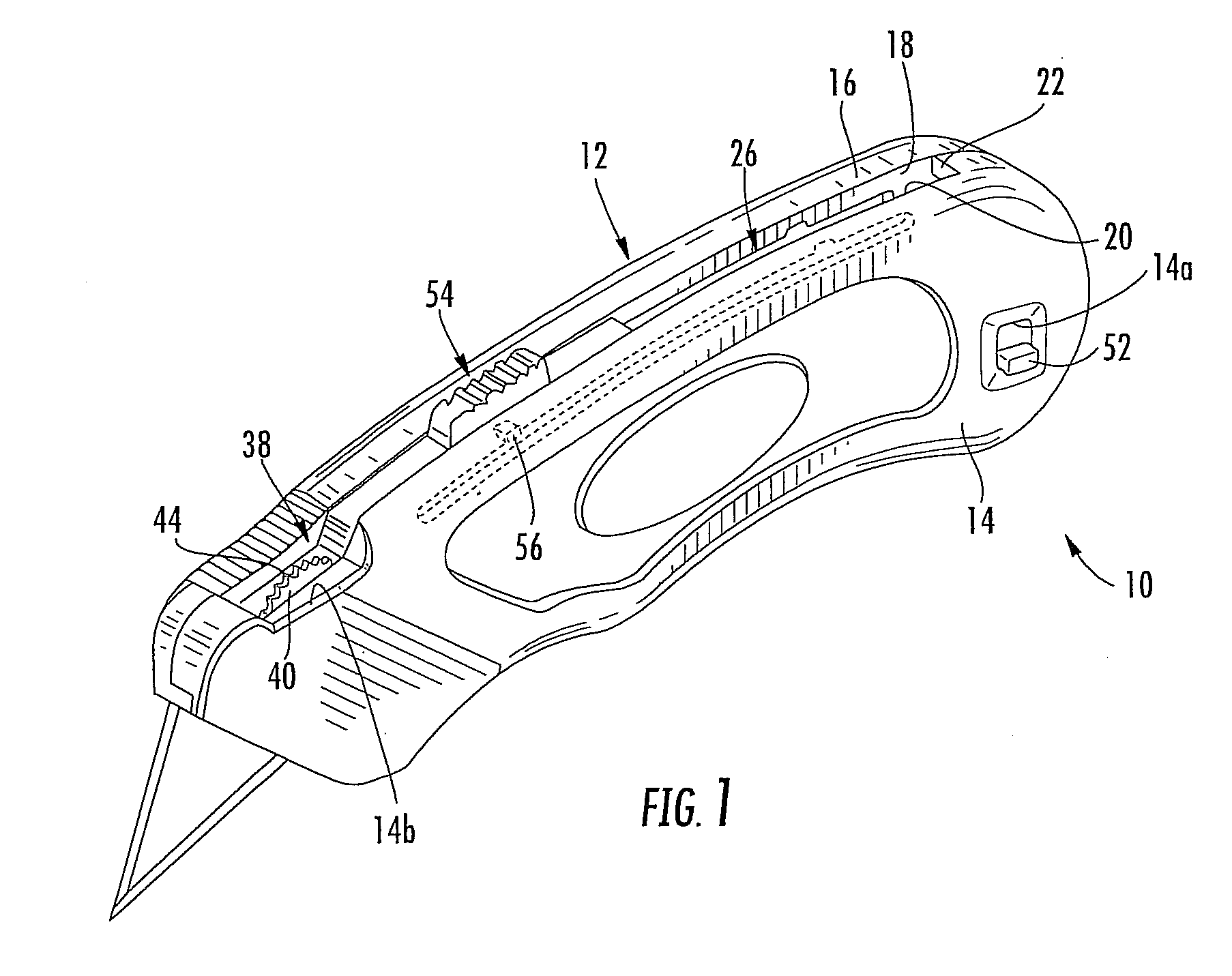
[0022]Referring now specifically to the Figures come up in which identical or similar parts as designated by the same reference numerals throughout, and further referring to FIG. 1, the self loading utility knife in accordance with the present invention is generally designated by reference numeral 10.

[0023]The utility knife 10 includes a handle 12 formed of a pair of complementary shells, a right shell 14 and a left shell 16, together forming a substantially enclosed clamped shell arrangement having a front aperture 12a (FIG. 4). The right shell 14 includes a lock slot 14(a) and the sign is shown. While the upper edge of the right shell 14 is generally smooth and slightly curved as shown there is provided a disc cut-out 14b at the front end of the handle 12, for reasons to be discussed.

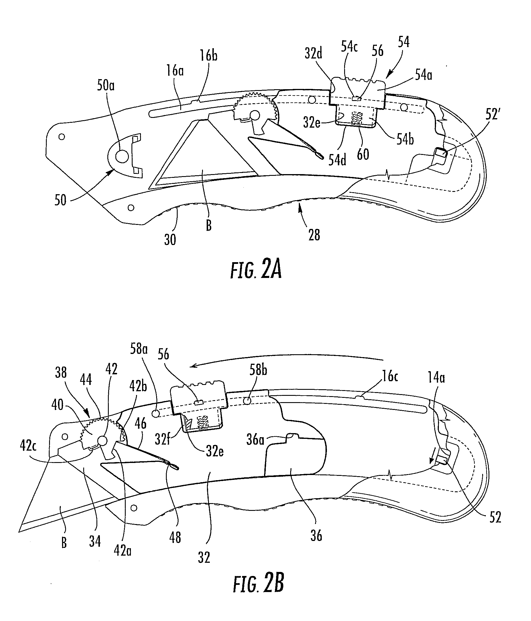
[0024]The left shell 16 is provided with an elongate recess 16a (FIGS. 2A, 2B) that generally extends from the rear end of the handle to the right end as shown and generally following the curvature of...


PUM


Abstract

A self-loading utility knife including an elongate handle having an internal chamber defining an axis and at one end is flat aperture for the passage of an active blade. The flat aperture defines a cutting plane extending through said handle along the axis. A blade-holder is slidably mounted in the chamber for movements in directions along the axis and is adapted to secure a single active blade for movement through the aperture when the blade holder is in the extended position. A blade-holder release button is coupled to the blade holder and is slidingly movable relative to the handle to move blade holder between retracted and extended positions. The handle has a blade compartment which is open to the chamber and can receive a stack of spare blades when a cover to the compartment is opened and blades can be shifted transversely relative to the axis into the chamber. The blade holder is provided with a recess having a depth no greater than the thickness of one blade to allow at least a portion of a single blade to be received in a retaining relationship within the recess to cause an end-most blade in the stack to be received within said recess to follow the movements of the blade holder. A spring biases the blades in the blade compartment inwardly in the direction of the blade holder. A blade releasing disc on the blade holder selectively locks a blade to the blade holder when the blade holder is in the extended position. The blade holder only receives a single blade within the recess. A belt clip s provided on the compartment cover.

Description

RELATED APPLICATIONS[0001]This application claims the priority benefit of U.S. Provisional Application No. 61 / 175,234 filed on May 4, 2009, which provisional application is hereby incorporated by reference in its entirety.BACKGROUND OF THE INVENTION[0002]1. Field of the Invention[0003]The present invention generally related to a hand tools, and more specifically to a self loading utility knife with a quick release blade mechanism.[0004]2. Description of the Prior Art[0005]Conventional utility knives have various types of structures including fixed, foldable and retractable. They are generally used to cut paper, fabric, and leather. The Chinese Patent Application No. 93208241.6 (Publication Date: Jun. 22, 1994) disclosed “a retractable rope-cut utility knife”, in which a blade stored in a handle is extended out step by step by moving a slider. However, it is not convenient to replace the blade. The Chinese Patent Application No. 03223149.0 (Publication Date: Dec. 24, 2003) disclosed ...

Claims


Application Information

Patent Timeline
IPC IPC(8): B26B3/00B26B3/06
CPCB26B5/001
Inventor HAO, WENDE, HUANG YUAN
Owner HAO WEN
Why Eureka
Try Eureka