Differential Pressure Sensor

a pressure sensor and differential technology, applied in the direction of fluid pressure measurement using elastically deformable gauges, instruments, fluid pressure measurement by mechanical elements, etc., can solve the problems of large internal oil volume and deterioration of measurements, and achieve precise definition of cutoff pressure, increase measurement accuracy, and less cost

Active Publication Date: 2010-11-11
BAKER HUGHES INC +1
View PDF11 Cites 10 Cited by
  • Summary
  • Abstract
  • Description
  • Claims
  • Application Information

AI Technical Summary

Benefits of technology

[0011]As apparent from the above, the configuration according to embodiments of the present invention is so that not only the two process diaphragms are exposed to the two respective external process environments, but also the two separating discs face outwardly against the respective two external environments. Since the two separating discs bear against abutment faces / stop faces with only a thin oil film located therebetween, the oil volumes which in the prior art existed between the process diaphragm and separating disc are replaced with volumes within the two process diaphragms, i.e. between each process diaphragm and an inner abutment face. As such a volume can be made much smaller than the volume necessary between two diaphragms, a significant oil volume is disposed of. This provides for increased measurement accuracy as well as a more precisely defined cutoff pressure.
[0012]Embodiments of the present invention provide a less expensive and more robust and accurate sensor. The oil volume may be kept at a minimum, and is less than half of the volume necessary when using an internal separating disc. Also, the process diaphragms do not need to service the volume needed by the separating disc(s), and the error contribution is reduced.

Problems solved by technology

The problem with this differential pressure sensor is that it contains large internal oil volumes.
This volume change must be compensated for by the process diaphragms, so that these introduce a pressure drop that will deteriorate the measurements.

Method used


Image

  • Differential Pressure Sensor
  • Differential Pressure Sensor
  • Differential Pressure Sensor

Examples


Embodiment Construction

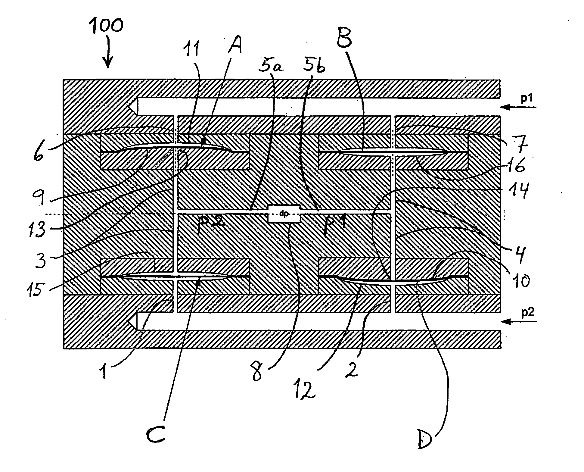
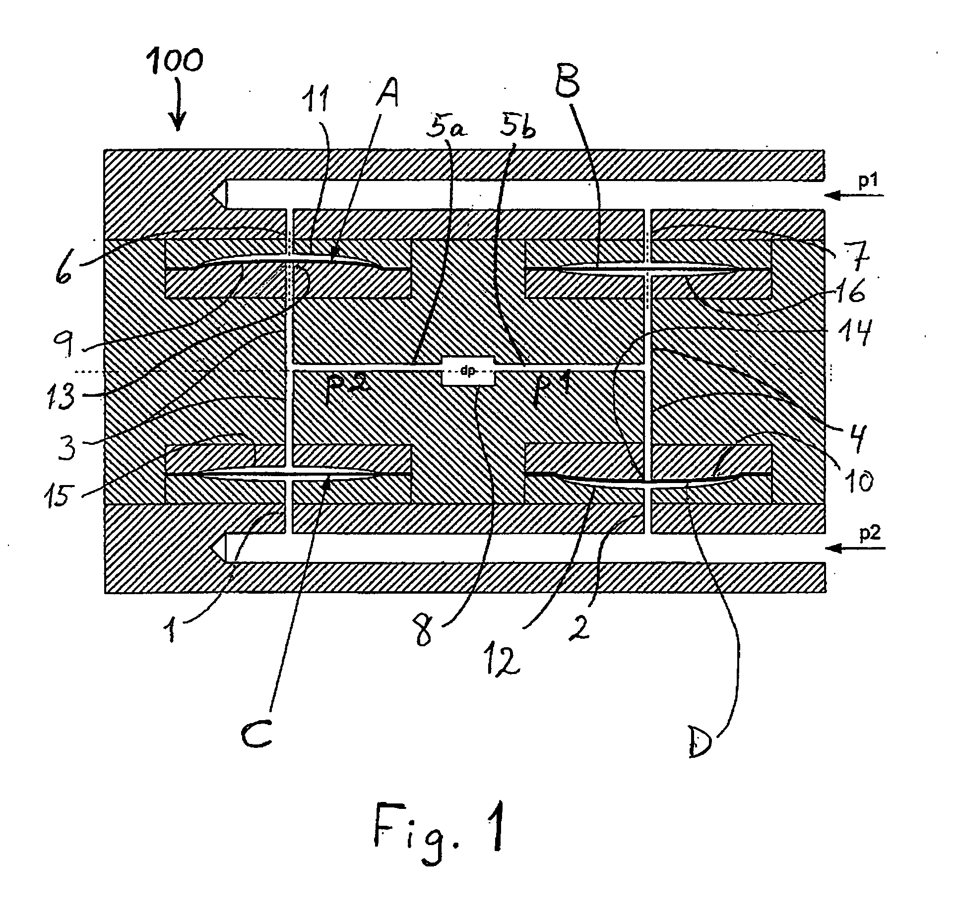
[0018]In FIG. 1 is illustrated a principle drawing of a possible embodiment of a differential pressure sensor according to the present invention. A housing or sensor block 100 contains symmetrically disposed channels 1-7 for transferring pressure to a differential pressure sensor element located in a central chamber 8. The internal channels 3-5 have a small cross-section so that the volume of a hydraulic oil with which they are filled is small.

[0019]The oil-filled internal channels 3-5 are shielded, by diaphragms, from two external environments with high pressures p1 and p2r respectively, as shown with arrows to the right in the figure. The purpose of the sensor is to measure the pressure differential, dp, between pressures p1 and p2 in such a manner that the sensor element itself, represented symbolically in the figure by the term dp in the central chamber 8, is not exposed to any of the external environments (with chemicals, temperatures) but only to pressure-transferring hydrauli...


PUM

PropertyMeasurementUnit
pressureaaaaaaaaaa
pressureaaaaaaaaaa
diameteraaaaaaaaaa

Abstract

A differential pressure sensor for measuring a pressure difference between two high-pressure environments is comprised of a sensor block including internal, oil-filled channels leading to an internally positioned differential pressure sensor element. Two process diaphragms are provided for transferring pressure from the high-pressure environments for isolating two distinct internal oil channels from the high-pressure environments. In order to achieve small internal oil volumes in the sensor block, additionally two separating discs, which initially separate between the two internal oil channels, are positioned in fluid communication with the high-pressure environments in order to block for the pressure from the high-pressure environments against the oil channels “from behind.” The separating discs bear against abutment faces having small openings into the internal oil channels. The separating discs are preferably given a pre-tension, and the abutment faces are then shaped correspondingly having a slightly convex shape. Preferably, separating discs with no corrugations are used.

Description

CROSS-REFERENCE TO RELATED APPLICATIONS[0001]This application is a 35 U.S. C. §371 national stage application of PCT Application No. PCT / NO2008 / 000199, filed 3 Jun. 2008, and entitled Differential Pressure Sensor, hereby incorporated herein by reference, which claims priority to Norwegian Patent Application No. 2007 2900, filed 8 Jun. 2007, hereby incorporated herein by reference.STATEMENT REGARDING FEDERALLY-SPONSORED RESEARCH OR DEVELOPMENT[0002]Not applicable.BACKGROUND[0003]U.S. Pat. No. 6,796,185 introductorily describes a differential pressure sensor based on older technology, wherein from a high-pressure side and a low-pressure side (actually two high pressures, with one pressure being higher than the other), two different pressures are transferred to two trapped oil volumes in channels within the sensor. A desire exists to protect an internally located differential pressure sensor (a) from being exposed to possible aggressive chemical substances, and (b) from being exposed t...

Claims


Application Information

Patent Timeline
Patent Type & Authority Applications(United States)
IPC IPC(8): G01L13/02
CPCG01L13/028G01L19/0618G01L19/0645
Inventor SEEBERG, BJORN ERIK
Owner BAKER HUGHES INC
Why Eureka
Try Eureka