
Bicycle bottom bracket force sensor

a technology for force sensors and bicycles, applied in the direction of force/torque/work measurement apparatuses, cycle equipments, instruments, etc., can solve problems such as complex arrangement, and achieve the effect of convenient installation and removal of bicycles

Inactive Publication Date: 2010-11-11
SHIMANO INC
View PDF19 Cites 53 Cited by
  • Summary
  • Abstract
  • Description
  • Claims
  • Application Information

AI Technical Summary

Benefits of technology

[0008]One object of the present invention is to provide a force sensor assembly that is easily installed and removed from a bicycle.

Problems solved by technology

However, this arrangement is complex and requires complete disassembly of the front crank assembly in order to install the force sensor.
One of the problems with this arrangement is that the sensor is exposed on the radially extending outer surface of the annular member prior to installation and can be damaged during the process of installing the annular member to the bottom bracket tube.

Method used


Image

  • Bicycle bottom bracket force sensor
  • Bicycle bottom bracket force sensor
  • Bicycle bottom bracket force sensor

Examples


Embodiment Construction

[0035]Selected embodiments of the present invention will now be explained with reference to the drawings. It will be apparent to those skilled in the art from this disclosure that the following descriptions of the embodiments of the present invention are provided for illustration only and not for the purpose of limiting the invention as defined by the appended claims and their equivalents.

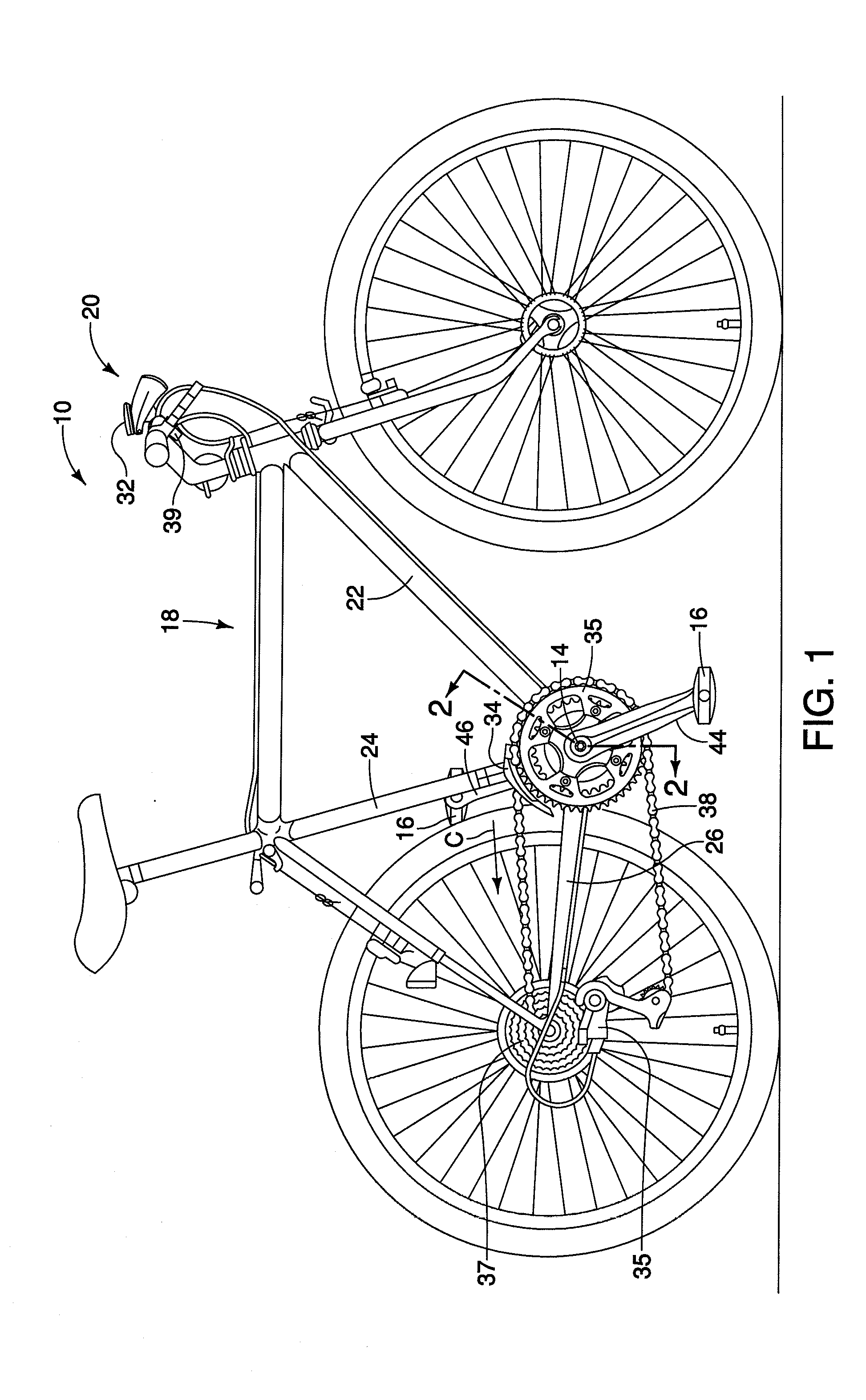
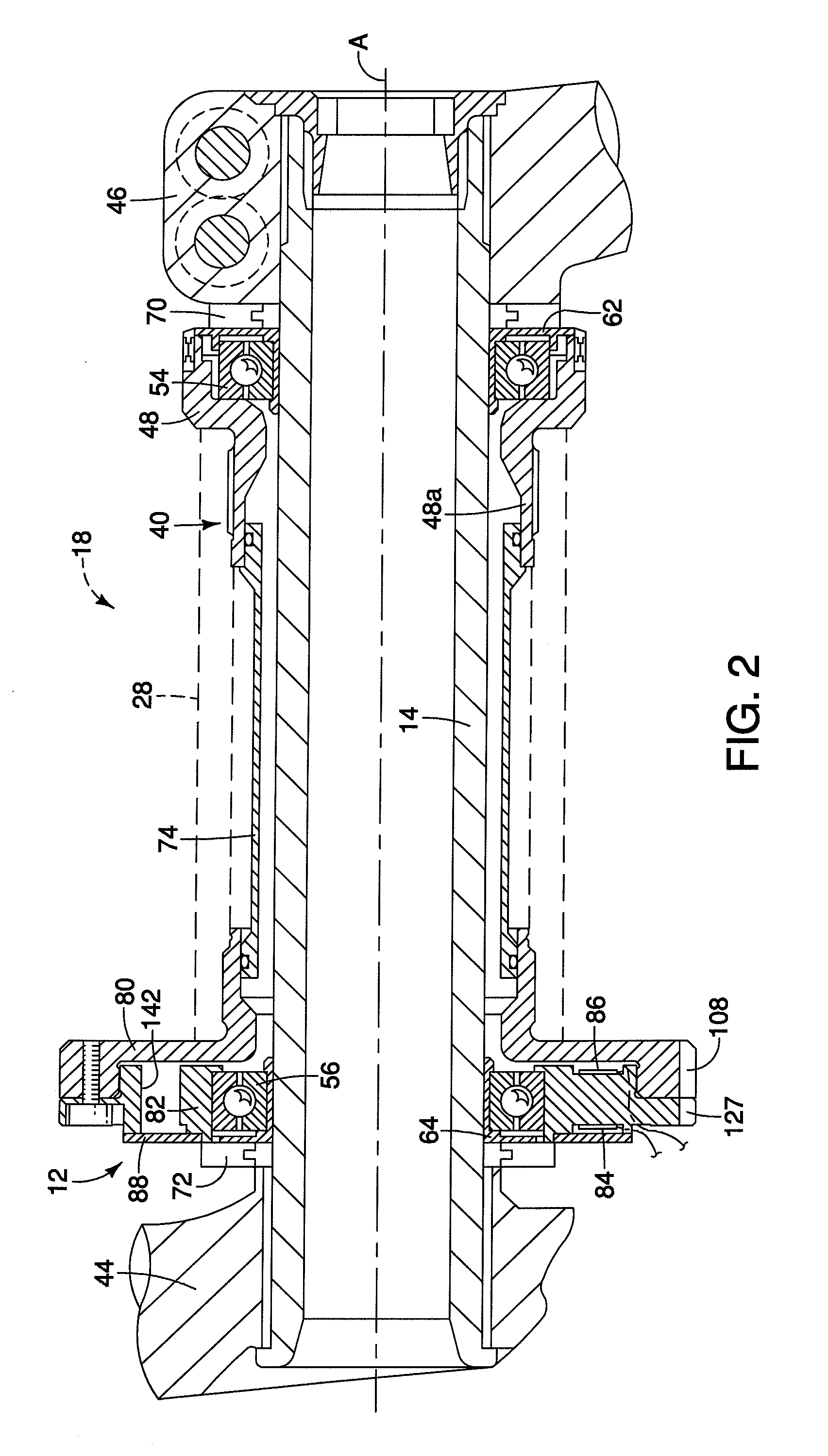
[0036]Referring initially to FIG. 1, a bicycle 10 that is illustrated in accordance with a first embodiment of the present invention. As shown in FIGS. 2 and 3, the bicycle 10 includes a force sensor assembly 12 that is configured to sense the force applied by a cyclist (not shown) on a crank axle 14 (shown in FIG. 2) as the cyclist applies force on a pair of bicycle pedals 16 (shown in FIG. 1) that are coupled to the crank axle 14. The bicycle pedals 16 include conventional binding devices configured to releasably retain cleats on cycling shoes (not shown) in a conventional manner. Specifically, w...


PUM

PropertyMeasurementUnit
angleaaaaaaaaaa
angleaaaaaaaaaa
angleaaaaaaaaaa

Abstract

A bicycle bottom bracket force sensor includes an outer portion, an inner portion, at least one sensor mounting surface and a strain gauge. The inner portion is dimensioned to receive and support a crank axle bearing that rotatably supports a crank axle. The at least one sensor mounting surface extends between the outer portion and the inner portion has the strain gauge fixed thereto. The sensor mounting surface extends in a direction substantially perpendicular to a rotation axis of the crank axle when the force sensor is coupled to the bicycle bottom bracket.

Description

BACKGROUND OF THE INVENTION[0001]1. Field of the Invention[0002]This invention generally relates to a force sensor for a bicycle. More specifically, the present invention relates to force sensor that mounts to an outer side of a bottom bracket of a bicycle that is used to calculate at least one of power applied to bicycle pedals and torque applied to a crank axle.[0003]2. Background Information[0004]Bicycling is becoming an increasingly more popular form of recreation as well as a means of transportation. Moreover, bicycling has become a very popular competitive sport for both amateurs and professionals. Whether the bicycle is used for recreation, transportation or competition, the bicycle industry is constantly improving the various components of the bicycle. Recently, bicycles have been provided with cycle computers to inform the rider of various traveling conditions of the bicycle.[0005]Bicycles are sometimes equipped with a force sensor (e.g., a torque-detecting device) for dete...

Claims


Application Information

Patent Timeline
Patent Type & Authority Applications(United States)
IPC IPC(8): G01L5/12
CPCB62K19/34G01L3/1457B62M3/003B62K2207/00B62J45/411B62J45/421B62J45/41B62J45/42
Inventor SASAKI, BUNGO
Owner SHIMANO INC
Features
  • Generate Ideas
  • Intellectual Property
  • Life Sciences
  • Materials
  • Tech Scout
  • Unparalleled Data Quality
  • Higher Quality Content
  • 60% Fewer Hallucinations
Learn More