Machine tool for turning operations

a technology of machine tools and turning operations, which is applied in the field of machine tools, can solve the problems of burdening the operator to change the workpieces on the machine tools, and achieve the effect of high utilization ratio

Active Publication Date: 2010-11-11
DMG MORI CO LTD
View PDF19 Cites 18 Cited by
  • Summary
  • Abstract
  • Description
  • Claims
  • Application Information

AI Technical Summary

Benefits of technology

[0010]It is an object of the present invention to provide a machine tool for turning operations which is capable of automatically changing workpieces by itself while the machine tool is carrying out a machining process, so that the machine tool does not need a workpiece changer and is not required to stop the machining process for changing workpieces, thereby increasing the utilization ratio thereof and serving as a labor saver.
[0011]Another object of the present invention is to provide a machine tool for turning operations which is capable of ejecting a workpiece which has been successively machined at opposite axial ends thereof, smoothly out of the machine tool by moving the workpiece obliquely downwardly by gravity without causing damage thereto.
[0039]The machine tool for performing at least turning operations according to the first-mentioned aspect of the present invention, which is constructed as described above, can automatically change the workpieces by itself while the machine tool is carrying out a machining process, so that the machine tool does not need a workpiece changer and is not required to stop the machining process for changing the workpieces. Therefore, the machine tool has a relatively high utilization ratio and serves as a labor saver. If the machine tool is combined with a workpiece transfer unit, then the machine tool can operate as an unattended automatic machine tool.
[0040]The machine tool for performing at least turning operations according to the other aspect of the present invention, which is constructed as described above, can eject a workpiece which has been successively machined at opposite axial ends thereof, smoothly out of the machine tool by moving the workpiece obliquely downwardly by gravity without causing damage thereto.

Problems solved by technology

In addition, it is burdensome for the operator to change the workpieces on the machine tools.

Method used


Image

  • Machine tool for turning operations
  • Machine tool for turning operations
  • Machine tool for turning operations

Examples


first embodiment

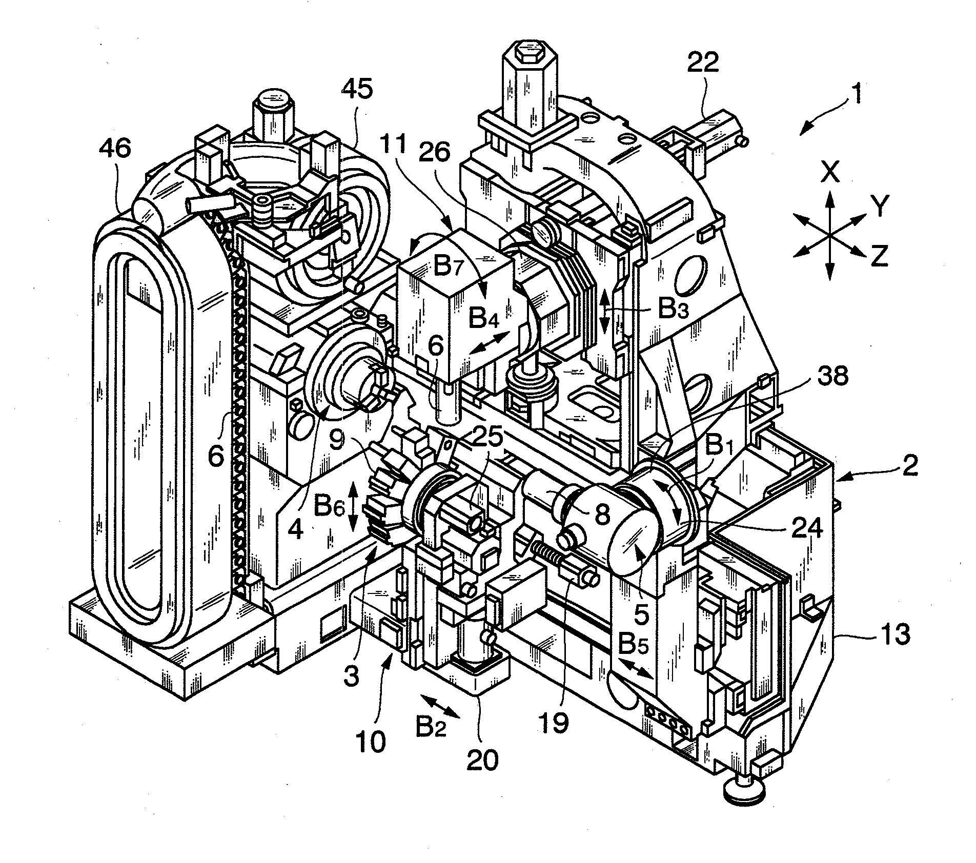
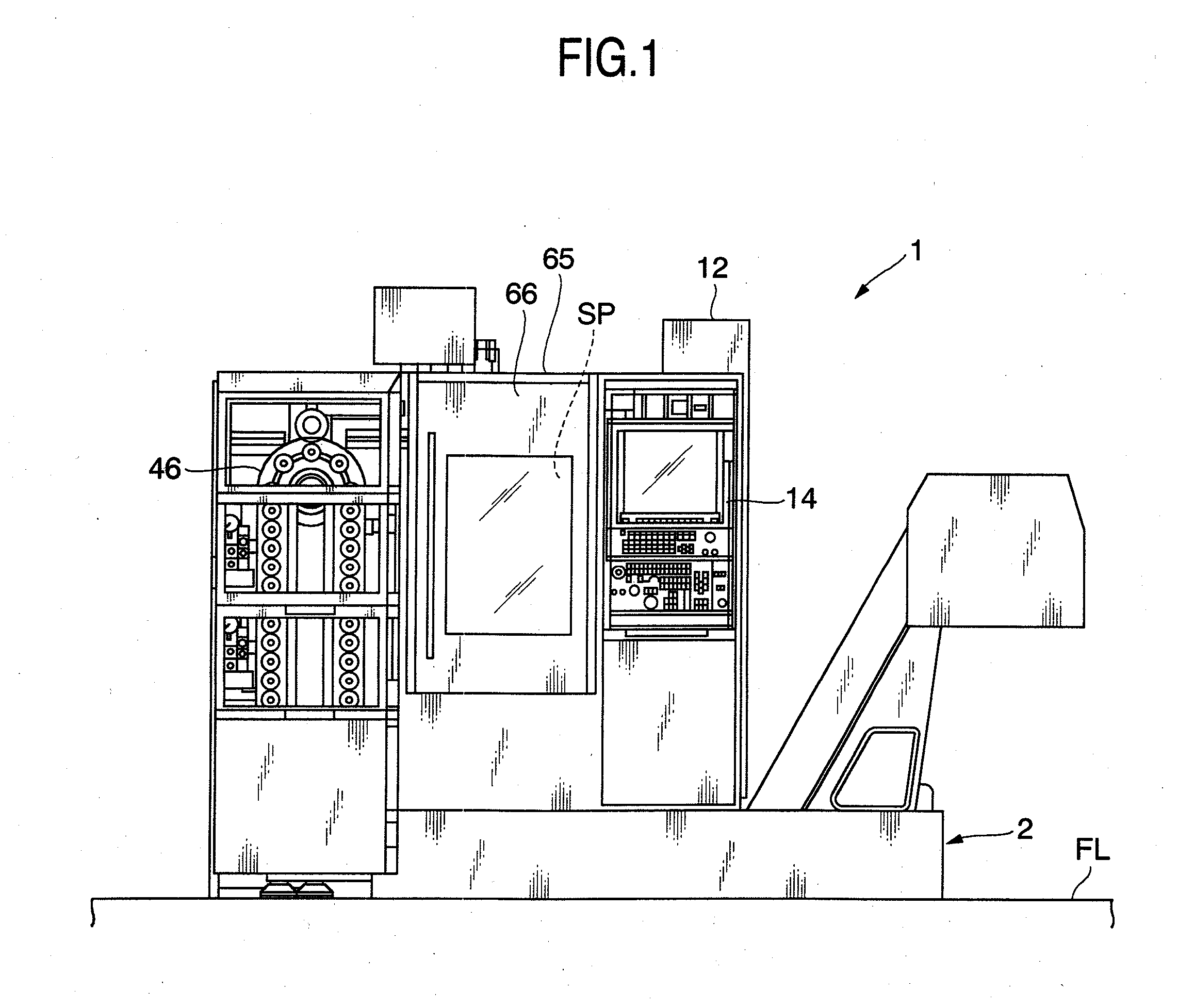
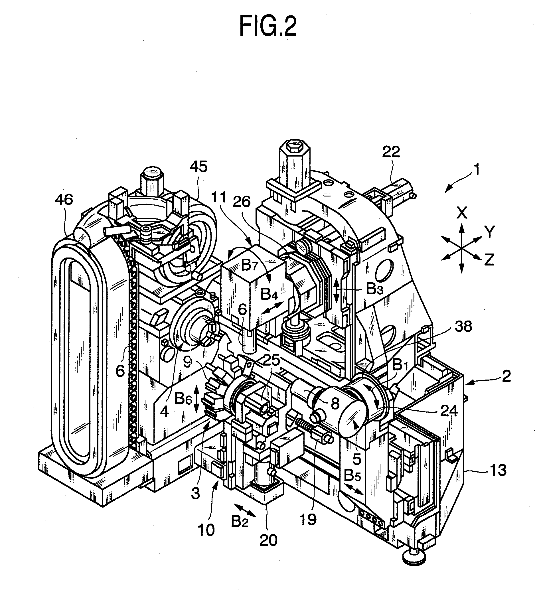
[0067]FIGS. 1 through 8D show a first embodiment of the present invention and a modification thereof. FIG. 1 is a front elevational view of a multi-axis turning center as a machine tool according to a first embodiment of the present invention, FIGS. 2 and 3 are perspective and front elevational views, respectively, of the multi-axis turning center shown in FIG. 1, FIG. 4 is a front elevational view of the multi-axis turning center shown in FIG. 1, showing the manner in which the multi-axis turning center is machining two workpieces simultaneously, FIGS. 5 and 6 are perspective and cross-sectional views, respectively, of a second headstock of the multi-axis turning center shown in FIG. 1, and FIGS. 7A through 7D are front elevational views showing a procedure from machining both ends of a workpiece with the multi-axis turning center shown in FIG. 1 to ejecting the workpiece from the multi-axis turning center.

[0068]As shown in FIGS. 1 through 6, the machine tool according to the first...

second embodiment

[0149]FIGS. 9 through 16 show a second embodiment of the present invention and modifications thereof. FIG. 9 is a front elevational view of a multi-axis turning center 1b as a machine tool according to a second embodiment of the present invention, FIG. 10 is a perspective view, similar to FIG. 5, of a second headstock 5a of the multi-axis turning center 1b, FIGS. 11A through 11D are front elevational views showing a procedure from machining both ends of a workpiece with the multi-axis turning center 1b to ejecting the workpiece from the multi-axis turning center 1b, and FIG. 12 is a front elevational view, similar to FIG. 4, of the multi-axis turning center 1b, showing the manner in which the multi-axis turning center 1b is machining two workpieces 8 simultaneously.

[0150]As shown in FIGS. 9 through 12, the multi-axis turning center 1b which serves as a machine tool for turning operations is of substantially the same structure as the multi-axis turning center 1 according to the first...


PUM

PropertyMeasurementUnit
angleaaaaaaaaaa
angleaaaaaaaaaa
gravityaaaaaaaaaa

Abstract

A multi-axis turning center for turning operations includes a machine body, a tool rest means for holding a tool, a first headstock for holding a workpiece, and a second headstock disposed in confronting relation to the first headstock, for holding a workpiece. The second headstock has a front chuck and a rear chuck for gripping respective workpieces. The second headstock performs a workpiece changing function by swiveling about a central axis. The multi-axis turning center is capable of automatically changing the workpieces by itself while it is carrying out a machining process, without the need for a workpiece changer. The multi-axis turning center does not need to stop its machining process for changing workpieces, resulting in an increase in the utilization ratio thereof.

Description

BACKGROUND OF THE INVENTION[0001]1. Field of the Invention[0002]The present invention relates to a machine tool for carrying out at least turning operations, which comprises a first headstock for holding a workpiece and a second headstock, which is disposed in confronting relation to the first headstock, for holding a workpiece.[0003]2. Description of the Related Art[0004]Japanese published patent application No. 5-57506 discloses a machining center for machining bars. The disclosed machining center has a rotating table (corresponding to a first headstock according to the present invention) for gripping a workpiece and another rotating table (corresponding to a second headstock according to the present invention), which is disposed in confronting relation to the first-mentioned rotating table, for gripping a workpiece.[0005]Japanese published patent application No. 7-88702 discloses a method of supplying a workpiece to and ejecting the workpiece from a lathe. According to the disclo...

Claims


Application Information

Patent Timeline
Patent Type & Authority Applications(United States)
IPC IPC(8): B23B3/06B23B3/16
CPCB23B3/30B23Q7/04B23Q39/048B23Q2230/006Y10T82/2564Y10T29/5114Y10T29/5153Y10T82/2508Y10T82/2552Y10T483/1705Y10T82/2514Y10T483/1707Y10T82/25Y10T82/2524
Inventor FUJIMOTO, KOJIKOMINE, KENTOTOKUMA, TSUTOMUNISHIMURA, YUTAKA
Owner DMG MORI CO LTD
Why Eureka
Try Eureka