Testing System and Testing Method

a testing system and electromagnetic shielding technology, applied in the direction of instruments, measurement devices, instrument screening arrangements, etc., can solve the problems of threatening the safety of the testing operator, affecting the accuracy of measurement results, so as to achieve smooth and efficient testing procedures

Active Publication Date: 2010-11-11
QUANTA COMPUTER INC
View PDF6 Cites 22 Cited by
  • Summary
  • Abstract
  • Description
  • Claims
  • Application Information

AI Technical Summary

Benefits of technology

[0016]Compared to prior art, in the testing system according to the invention, the pick-and-place device and the testing platform respectively have the corresponding electromagnetic shielding plate and the electromagnetic shielding chamber to form the isolated space for isolating the DUT. Accordingly, the testing system in the invention needs not huge-sized isolating box, and it can accomplish electromagnetic shielding within a compact space. Besides, the actions of placing and electromagnetic shielding the DUT in the invention are both completed by the pick-and-place device at the same time. That is to say, the testing method in the invention is capable of ensuring a smooth and efficiency testing procedure, and it can be widely applied to various DUTs with I / O pins on single side or on both sides.
[0017]The advantage and spirit of the invention may be understood by the following recitations together with the appended drawings.

Problems solved by technology

Especially in the wireless radio application, e.g. radio frequency identification (RFID), the radio frequency integrated circuit (RFIC) and RF circuitry are easy to be interfered by other electronic devices around, such that it spoils the measurement and even threaten the safety of the testing operator.
However, the metal isolating box is costly and huge in size.
It makes the testing procedure of the IC module in prior art time-consuming and inefficient.
In other word, when the DUT with signal pins on different surfaces is tested by the traditional testing system, it takes extra steps or processes to complete the whole procedure, and then it reduce the efficiency of the testing system.

Method used


Image

  • Testing System and Testing Method
  • Testing System and Testing Method
  • Testing System and Testing Method

Examples


Embodiment Construction

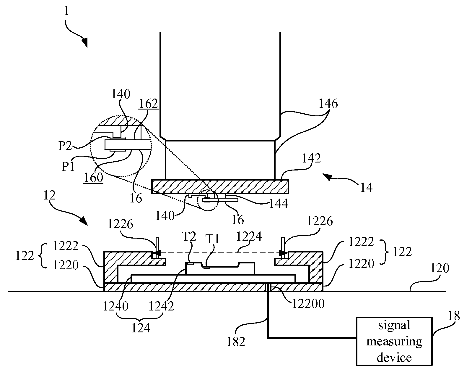
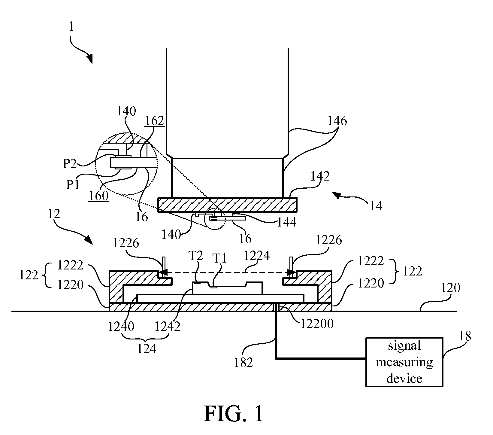
[0022]Please refer to FIG. 1. FIG. 1 is a schematic diagram illustrating a testing system 1 according to an embodiment of the invention. As shown in FIG. 1, the testing system 1 in the embodiment includes a testing platform 12, a pick-and-place device 14 and signal measuring device 18. The testing system 1 is used for testing the device under test (DUT) 16.

[0023]In the embodiment, the DUT 16 can be an IC component. In another embodiment, the DUT 16 can also be an IC module. The IC module may include an IC component, a print circuit board (PCB) and some active or passive components in need. In other words, the testing system 1 in the invention can be applied in testing various electronic assemblies at component or module level. The DUT 16 in this embodiment may has a first signal pin P1 and a second signal pin P2. The first signal pin P1 is disposed on a lower surface 160 of the DUT 16. The second signal pin P2 is disposed on an upper surface 162 of the DUT 16. In other words, the DU...


PUM


Abstract

The invention discloses a testing system and a testing method, suitable for testing a DUT with double-sided signal pins. The testing system includes a testing platform and a pick-and-place device. The testing platform includes an electromagnetic shielding chamber and a test-bench module. The electromagnetic shielding chamber has an opening. The test-bench module is disposed in-between the electromagnetic shielding chamber. The pick-and-place device is movably disposed above the testing platform. The pick-and-place device includes an electromagnetic shielding cap and a signal transmission structure. When the pick-and-place device places the DUT on the test-bench module, the electromagnetic shielding cap cooperates with the electromagnetic shielding chamber of the testing platform to form an isolated space for isolating the DUT, and furthermore, the signal pin disposed on an upper surface of the DUT can be electrically connected to the test-bench module through the signal transmission structure.

Description

BACKGROUND OF THE INVENTION[0001]1. Field of the Invention[0002]The invention relates to a testing system and a testing method, and more particularly, to a testing system and a testing method with electromagnetic shielding utility.[0003]2. Description of the Prior Art[0004]With the rocketing development of the semiconductor technology, the four steps of designing, manufacturing, packeting and testing in producing an IC module are now individual professional subjects. With more complex structures, more functionalities and more demanding of preciseness, the testing skill of the IC module becomes a critical and necessary technique in ensuring the yield rate and speeding up the producing procedures.[0005]In prior art, for maintaining high efficiency and stabilization in the IC module testing, it requires some specific testing instruments for holding the IC module under test, measuring signals and avoiding outer noises. There are many micro-sized IC modules appeared in many applications,...

Claims


Application Information

Patent Timeline
Patent Type & Authority Applications(United States)
IPC IPC(8): G01R31/02
CPCG01R1/18G01R1/0466G01R1/045
Inventor SHEN, LEE-CHENG
Owner QUANTA COMPUTER INC
Why Eureka
Try Eureka