
Voltage detection device

a voltage detection and voltage technology, applied in the direction of gain control, amplification control details, instruments, etc., can solve the problems of high labor intensity, large time consumption, and the operation of the voltage detection device described above involves a problem

Inactive Publication Date: 2010-11-11
HIOKI DENKI KK
View PDF9 Cites 50 Cited by
  • Summary
  • Abstract
  • Description
  • Claims
  • Application Information

AI Technical Summary

Benefits of technology

[0009]Unfortunately, the voltage detection device described above involves a problem as described below. That is to say, the voltage detection device requires independently calculating the static capacitance between the shield electrode and the ground (i.e., the first static capacitance described above) as well as the static capacitance between the detecting electrode and the conductor of the cable (i.e., the third static capacitance described above), and then operation of detecting the voltage imposed on the conductor requires great care and takes much time.

Problems solved by technology

Unfortunately, the voltage detection device described above involves a problem as described below.
That is to say, the voltage detection device requires independently calculating the static capacitance between the shield electrode and the ground (i.e., the first static capacitance described above) as well as the static capacitance between the detecting electrode and the conductor of the cable (i.e., the third static capacitance described above), and then operation of detecting the voltage imposed on the conductor requires great care and takes much time.

Method used


Image

  • Voltage detection device
  • Voltage detection device
  • Voltage detection device

Examples


first embodiment

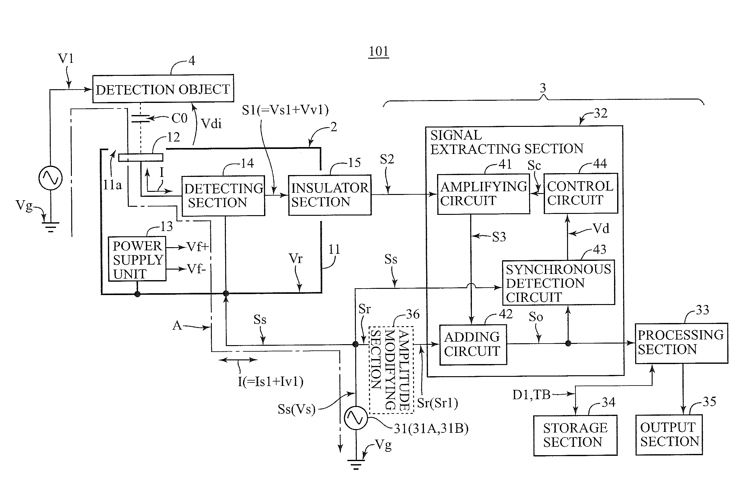
[0070]At first, with reference to the accompanying drawings, here is described a voltage detection device 101 of a first embodiment in accordance with the present invention.

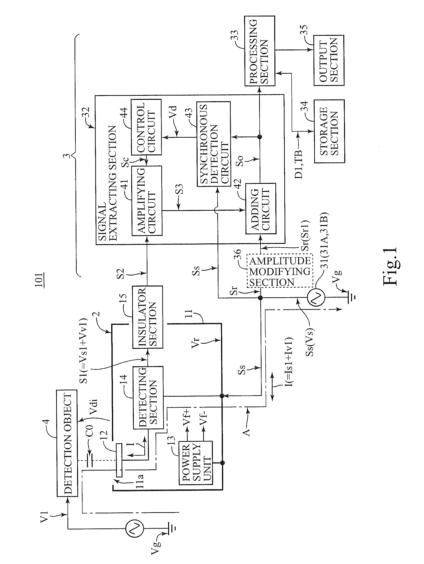
[0071]The voltage detection device 101 is a contact-free type voltage detection device comprising, as shown in FIG. 1, a floating circuit section 2 and a main circuit section 3.

[0072]The voltage detection device 101 is configured to be able to detect, by taking a ground electric potential Vg as a reference, an AC voltage V1 (an objective AC voltage) arising on a detection object 4 without physical contact.

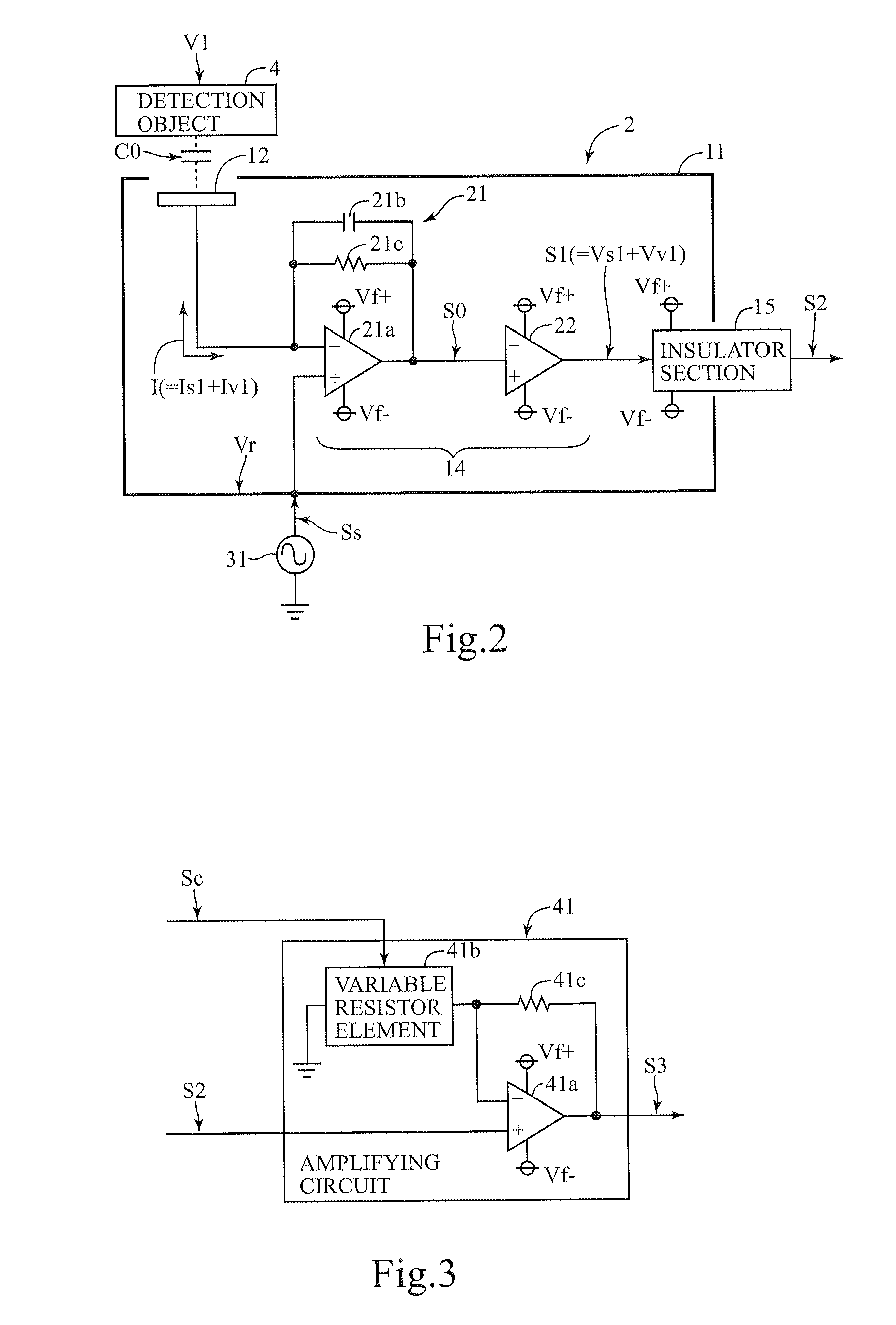
[0073]As shown in FIG. 1, the floating circuit section 2 includes a guard electrode 11, a detecting electrode 12, a power supply unit 13, a detecting section 14, and an insulator section 15. The guard electrode 11, being constructed with a conductive material (e.g., a metal material) and configured as a reference voltage section in the floating circuit section 2, internally accommodates the detecting electrode 1...

second embodiment

[0102]A voltage detection device 102 of a second embodiment in accordance with the present invention includes a detection electrode 12 and a detecting section 14A instead of the floating circuit section 2 of the voltage detection device 101, as shown in FIG. 4. Namely, the voltage detection device 102 comprises the detection electrode 12, the detecting section 14A and the main circuit section 3. The voltage detection device 102 is configured to be able to detect the AC voltage V1 arising on the detection object without physical contact. With respect to the detection electrode 12 and the main circuit section 3, the same configuration as that of the voltage detection device 101 is applied. Then, these components are provided with the same reference numerals, and any redundant explanation is omitted. Explanation is mainly given regarding the detecting section 14A that is placed differently from the voltage detection device 101.

[0103]The detecting section 14A is supplied with voltages f...

third embodiment

[0149]A voltage detection device 103 of a third embodiment in accordance with the present invention is a contact-free type voltage detection device comprising, as shown in FIG. 13, a floating circuit section 2 and a main circuit section 3A. The voltage detection device 101 is configured to be able to detect, by taking a ground electric potential Vg as a reference, an AC voltage V1 (an objective AC voltage) arising on a detection object 4 without physical contact. Except configuration of a signal extracting section 32A of the main circuit section 3A and operation of a processing section 33A, the configuration and operation of the voltage detection device 103 are the same as those of the voltage detection device 101 shown in FIG. 1. Then, all the same components are provided with the same reference numerals, and any redundant explanation is omitted. Explanation is mainly given regarding the signal extracting section 32A and the processing section 33A that are placed differently from t...


PUM


Abstract

A voltage detection device detects an objective AC voltage arising on a detection object. The voltage detection device includes; a detecting electrode placed so as to be capacitively coupled with the detection object; a reference signal output section for outputting a reference signal; a detecting section outputting a detection signal changing its amplitude in accordance with both current values of a detection object current flowing according to the objective AC voltage and a reference current flowing according to the reference signal; and a signal extracting section for extracting a signal component of the objective AC voltage from an amplified detection signal and outputting the signal component as an output signal, the amplified detection signal being obtained through controlling a gain for amplifying the detection signal so as to make a signal component of the reference signal included in the detection signal have a predetermined value.

Description

CROSS-REFERENCE TO RELATED APPLICATION[0001]The present application claims priority from Japanese Patent Applications No. 2009-110304 filed on Apr. 30, 2009, No. 2009-116546 filed on May 13, 2009, No. 2009-169731 filed on Jul. 21, 2009, No. 2009-180785 filed on Aug. 3, 2009, No. 2010-69677 filed Mar. 25, 2010, No. 2010-69695 filed on Mar. 25, 2010, and No. 2010-69714 filed on Mar. 25, 2010, the contents of which are incorporated herein by reference.BACKGROUND OF THE INVENTION[0002]1. Field of the Invention[0003]The present invention relates to a contact-free type voltage detection device for detecting an objective AC voltage of a detection object without physical contact.[0004]2. Description of Related Art[0005]Known as this type of voltage detection device is a contact-free type voltage-measuring unit (hereinafter also called a “voltage detection device”) disclosed in Patent Document 1: Japanese Patent Publication No. 3158063 (Pages 4 through 6, and FIG. 3). The voltage detection d...

Claims


Application Information

Patent Timeline
IPC IPC(8): H03G1/00
CPCG01R19/2503G01R19/0084G01R15/06
Inventor YANAGISAWA, KOICHI
Owner HIOKI DENKI KK
Learn More