
Systems and methods for effective relative intensity noise (RIN) subtraction in depolarized gyros

a technology of relative intensity noise and subtraction method, which is applied in the direction of speed measurement using gyroscopic effects, instruments, surveying and navigation, etc., can solve the problems of significant degradation of rin subtraction efficiency, ineffective rin subtraction, depolarized gyroscope, etc., to improve the arw performance of depolarized gyros, more effective rin subtraction, and more efficient noise subtraction

Inactive Publication Date: 2010-11-11
HONEYWELL INT INC
View PDF17 Cites 13 Cited by
  • Summary
  • Abstract
  • Description
  • Claims
  • Application Information

AI Technical Summary

Benefits of technology

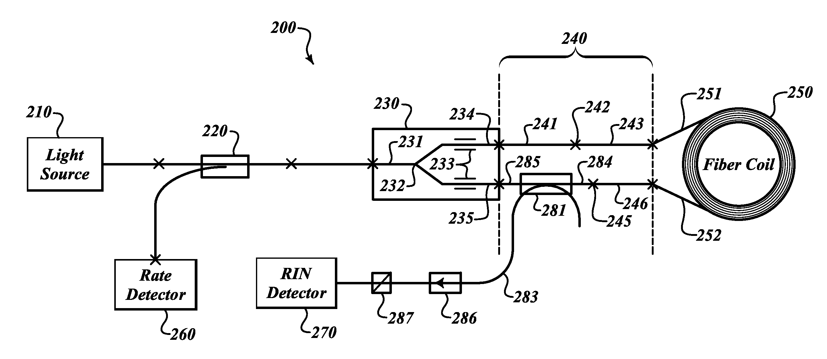
[0004]The present invention provides a more effective RIN subtraction method which will significantly improve the ARW performance of the depolarized gyros. This invention uses a scheme that taps the RIN detector light in the sensing loop, after the light transits through the depolarizer and the coil but before it combines with the counter propagating lightwave. The tapped RIN lightwaves are polarized by a following polarizer with pass axis orientated in the same direction as that of the IOC. In this way, the RIN detector receives lightwaves with spectrum substantially identical to that of the rate detector, leading to more effective RIN subtraction. Since the rotation and modulation induced lightwave phase variations are not converted to intensity variations at the RIN detector (interference with the counter propagating light does not happen), only the unwanted intensity noise is subtracted out from the rate signal. This scheme has an additional advantage of easy satisfaction of the delay requirement of the RIN signal relative to the rate signal without using a long delay fiber or additional electronics. Furthermore, since the RIN signals are tapped after the light transit through the coil fiber (up to a few kilometers), the intensity fluctuations originated from changes of coil loss are identical to both rate and RIN detector, leading to more efficient noise subtraction.
[0005]In the present invention, there are two preferred embodiments of the invention. One is to insert a PM-coupler at one of the IOC output fibers connected to the depolarizer. This coupler couples a small amount of light that transits through the coil and directs it to the RIN detector. Properly polarizing the RIN light and isolating it from returning to the sensing loop are necessary. Another embodiment requires a new design of the integrated optical circuit (IOC) which incorporates the RIN tap coupler and the polarizer inside the IOC. This scheme increases the level of component integration and helps to realize a more compact gyro design.

Problems solved by technology

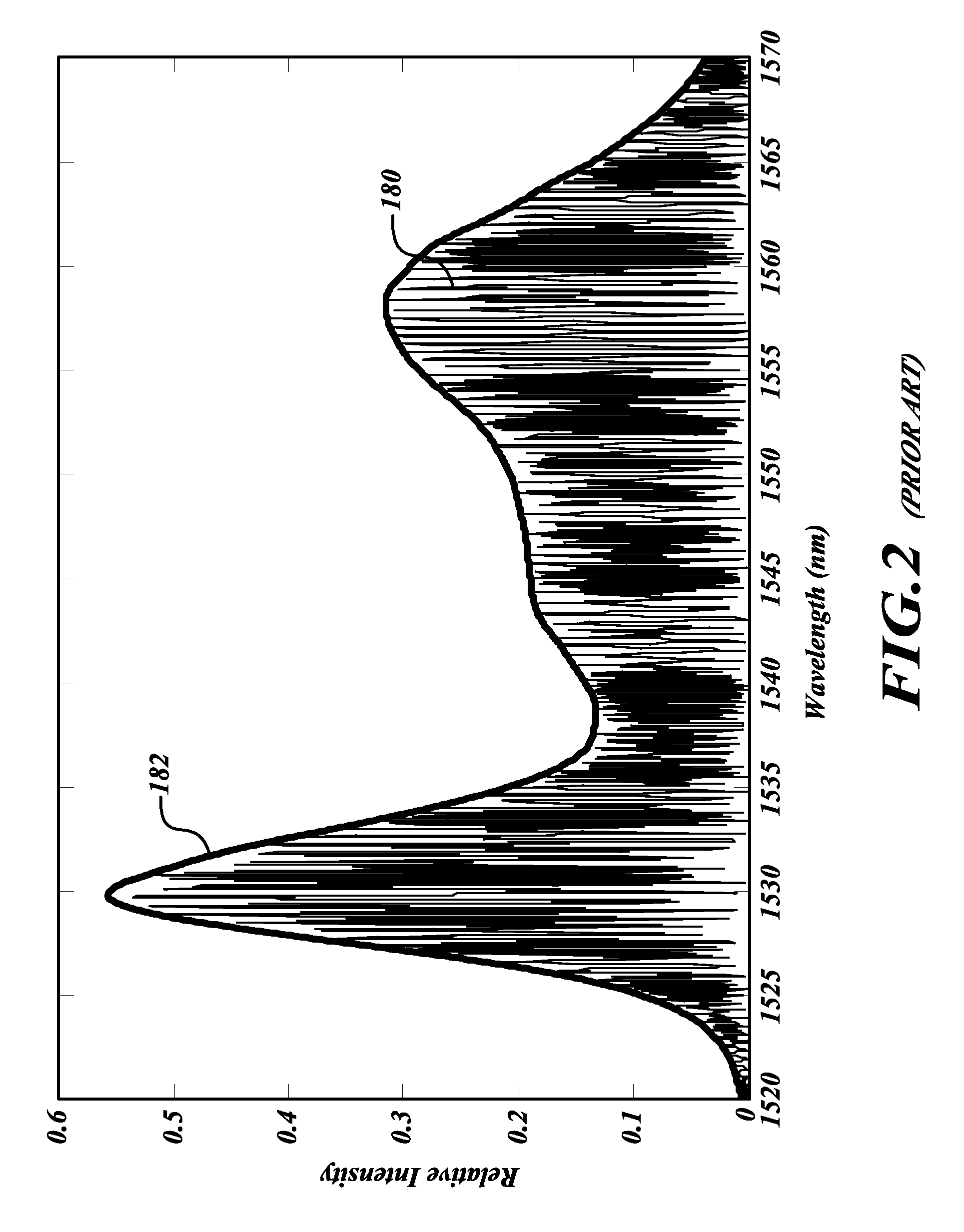
However, for depolarized single mode (SM) IFOGs, the RIN subtraction has not been as effective as that for polarization maintaining (PM) IFOGs due to mismatch between the lightwave spectra at the RIN detector and that at the rate detector.
However, this is not the case for the depolarized gyroscope.
This spectral mismatch between rate and RIN causes significant degradation of RIN subtraction efficiency.

Method used


Image

  • Systems and methods for effective relative intensity noise (RIN) subtraction in depolarized gyros
  • Systems and methods for effective relative intensity noise (RIN) subtraction in depolarized gyros
  • Systems and methods for effective relative intensity noise (RIN) subtraction in depolarized gyros

Examples


Embodiment Construction

[0011]Relative intensity noise (RIN) of a broadband light source originates from beating of the different optical frequency components contained in the light source. For an interferometric fiber optic gyroscope (IFOG), the RIN at the rate detector is determined by the light source spectrum reached the detector. In order to effectively subtract the intensity noise from the rate detector, another detector (RIN detector) dedicated to record the RIN of the light source at a different place of the optical circuit is desirable to receive light with substantially the same spectrum as that of the rate detector. The present invention describes systems and methods for effective RIN subtraction in depolarized gyros using matched light spectra at RIN and rate detectors.

[0012]Referring to FIG. 3, according to one embodiment of the present invention, a depolarized gyro 200 includes a light source 210, a directional coupler 220, an integrated optical circuit (IOC) 230, and a fiber loop 250. These ...


PUM


Abstract

Effective relative intensity noise (RIN) subtraction systems and methods for improving ARW performance of a depolarized gyros. This invention taps the RIN detector light in the sensing loop, after the light transmits through the depolarizer and the coil but before it combines with the counter propagating lightwave. The tapped RIN lightwaves are polarized with pass-axis orientated in the same direction as that of the IOC, so that the RIN detector receives lightwaves with spectrum substantially identical to that of the rate detector, leading to more effective RIN subtraction.

Description

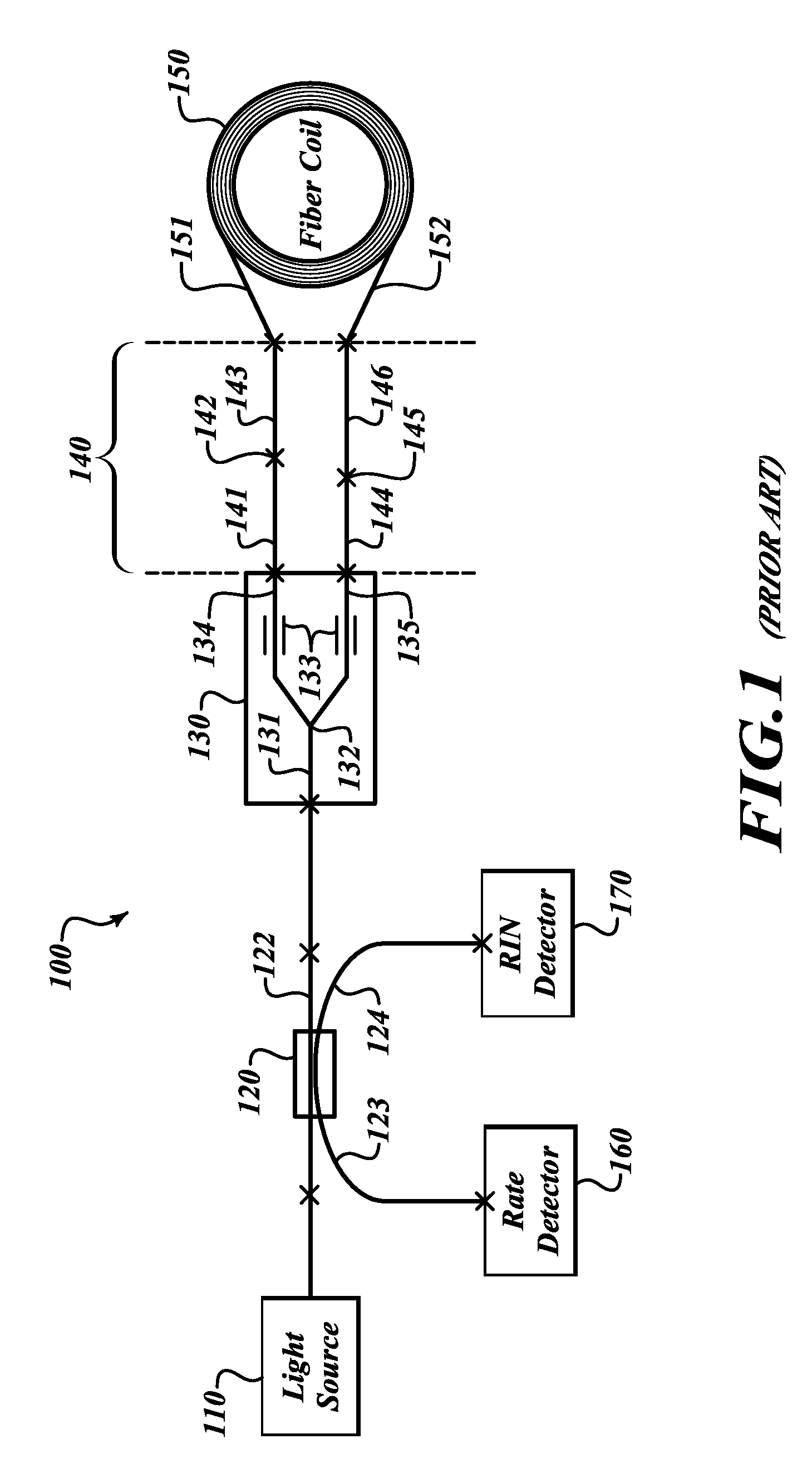
BACKGROUND OF THE INVENTION[0001]Relative intensity noise (RIN) is one of the major contributors to interferometric fiber optic gyro (IFOG) angle random walk (ARW). Electric intensity-noise-subtraction has been used to reduce the RIN in order to improve the gyro performance. However, for depolarized single mode (SM) IFOGs, the RIN subtraction has not been as effective as that for polarization maintaining (PM) IFOGs due to mismatch between the lightwave spectra at the RIN detector and that at the rate detector. This spectrum mismatch is originated from the gyro depolarizer and the birefringence of the single mode coil fiber.[0002]FIG. 1 shows a typical prior art RIN subtraction scheme in a depolarized fiber optic gyroscope 100. The lightwave emit from a light source 110 is directed by a 2×2 fiber coupler 120 into the input waveguide 131 of an integrated optical circuit (IOC) 130. A Y junction splitter / combiner 132 of the IOC splits the input lightwaves into substantially equal parts,...

Claims


Application Information

Patent Timeline
Patent Type & Authority Applications(United States)
IPC IPC(8): G01C19/72
CPCG01C19/721
Inventor QIU, TIEQUNSANDERS, STEVEN J.NARAYANAN, CHELLAPPAN
Owner HONEYWELL INT INC
Learn More