
Apparatus and method for portable calibration of electrofusion controllers

Active Publication Date: 2010-11-18
EF TECH
View PDF37 Cites 6 Cited by
  • Summary
  • Abstract
  • Description
  • Claims
  • Application Information

AI Technical Summary

Benefits of technology

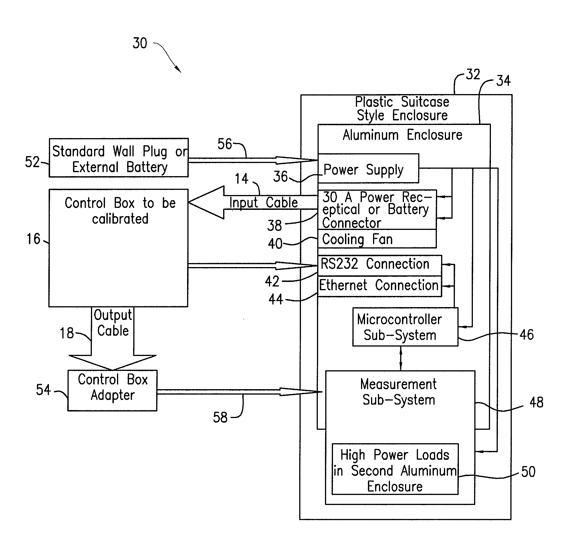
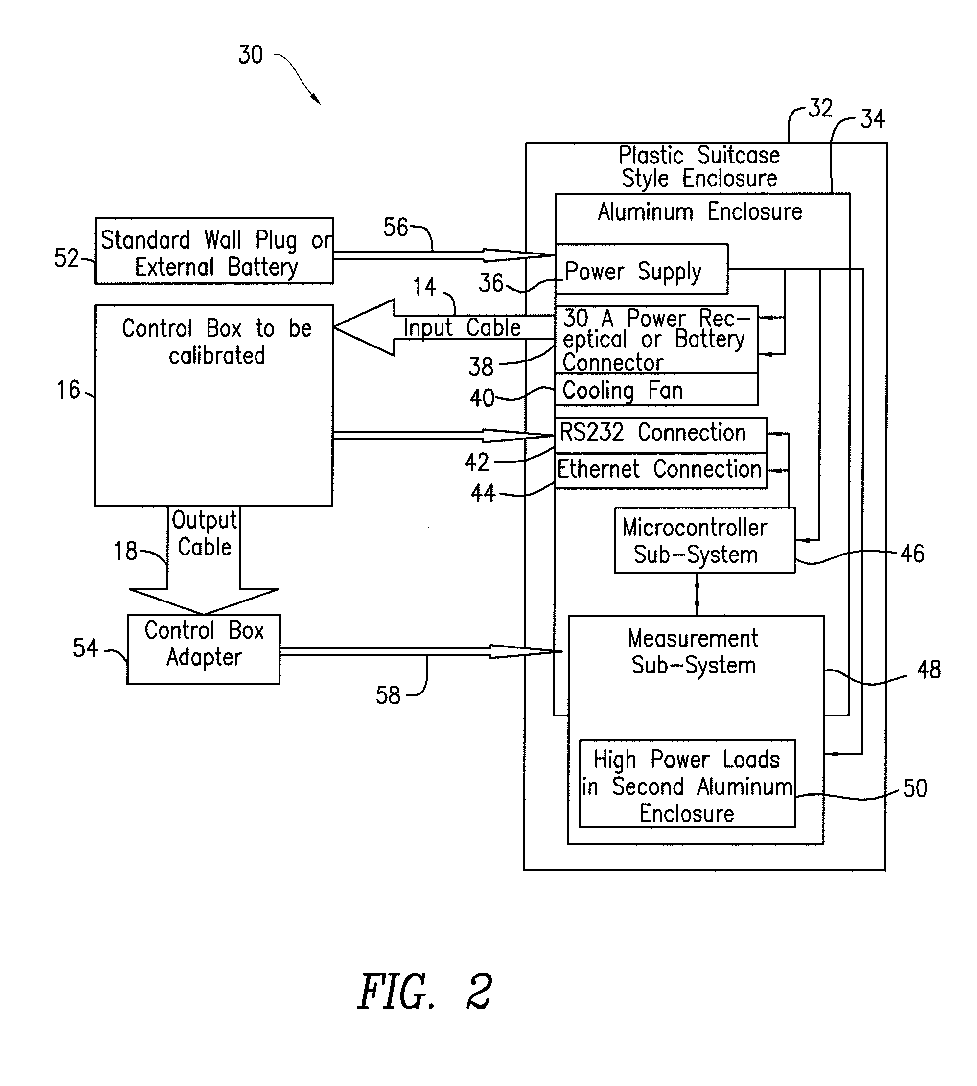
[0006]The present invention relates to an apparatus and method for portable calibration of electrofusion controllers. A portable self-contained calibration device is provided, which presents an electrofusion controller with dummy loads to simulate real fittings to be fused. The calibration device instructs the electrofusion controller to apply electricity to the dummy load. Then, the calibration device measures parameters outputted by the electrofusion controller (such as voltage, current, and time) with predefined parameters. If there is a difference between the expected value and the measured values, the calibration device adjusts the electrofusion controller's memory. The measurement is repeated with a second independent measurement device to provide accuracy. The calibration device of the present invention therefore allows for field calibration of electrofusion controllers, thereby obviating the need to ship such controllers to remote locations.

Problems solved by technology

If the amount of energy provided is too small, the fitting will not be properly bonded to the pipe.
If the amount of energy provided is too large, the plastic itself will begin to degrade.
If the fusion is not properly controlled, the resulting joint will be faulty and could fail a pressure test before being put into service, or worse, prematurely fail when put into service.
The resultant “down time” usually lasts one or more weeks (including time in transit), which is undesirable and can cost customers shipping fees and lost productivity.

Method used


Image

  • Apparatus and method for portable calibration of electrofusion controllers
  • Apparatus and method for portable calibration of electrofusion controllers
  • Apparatus and method for portable calibration of electrofusion controllers

Examples


Embodiment Construction

[0019]The present invention relates to an apparatus and method for remote calibration of electrofusion controllers, as described in detail below with reference to FIGS. 1-11. As used herein, the term “control box” is also used to refer to an electrofusion controller. Furthermore, the terms “remote” and “portable” are used interchangeably throughout the application.

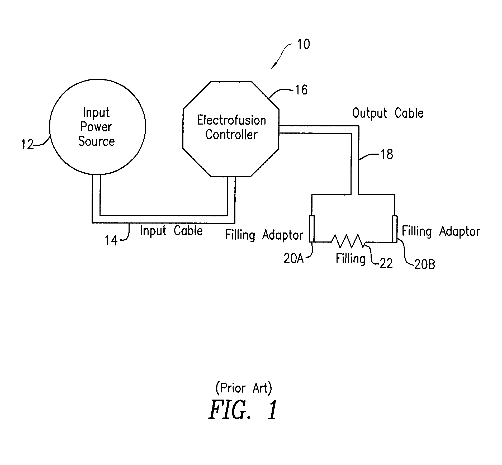
[0020]FIG. 1 is a block diagram showing a typical electrofusion control system implemented in a typical installation, indicated generally at 10. The installation 10 includes an input power source 12 connected via a input cable 14 to a electrofusion controller 16, which is connected via an output cable 18 to fitting adaptors 20a-20b placed on a fitting 22. Of course, the arrangement and number of components shown in FIG. 1 could be varied as desired without departing from the spirit or scope of the present invention. The electrofusion controller 16 provides the required energy to properly heat the element embedded in the fi...


PUM

PropertyMeasurementUnit
Timeaaaaaaaaaa
Electrical resistanceaaaaaaaaaa
Currentaaaaaaaaaa

Abstract

An apparatus and method for portable calibration of electrofusion controllers. The method includes providing a portable self-contained calibration device to an electrofusion controller. The calibration device includes internal or external dummy loads to simulate real fittings to be fused and instructs the electrofusion controller to apply electricity to these dummy load. Then, the calibration device uses a measurement sub-system to measure a pre-determined parameter. A microcontroller sub-system determines if there is a difference between the measured values and the expected values. If there is a difference, the calibration device adjusts the electrofusion controller's memory. The calibration device repeats the measurement with a second independent measurement device to ensure accuracy.

Description

FIELD OF THE INVENTION[0001]The present invention relates generally to calibration equipment. More specifically, the present invention relates to portable calibration equipment for calibrating electrofusion controllers.BACKGROUND OF THE INVENTION[0002]It is known in the welding industry to use electric heat-weldable fittings (also known as electrofusion fittings) formed of thermoplastic materials to fuse two pipe segments together. Such fittings generally include an electrically resistive heating coil or element positioned adjacent to the inside surfaces of the fitting which are to be welded to one or more other thermoplastic members, such as plastic pipe sections. The electrically resistive heating element typically comprises a coil of wire positioned in the thermoplastic material of the fitting, which is connected to electric contacts attached to an outside surface of the fitting. Electrofusion is an effective method for installing branch connections in pipelines, as well as for t...

Claims


Application Information

Patent Timeline
IPC IPC(8): G01D18/00
CPCB23K13/025B29C66/91653B23K2201/06B29C65/342B29C66/522B29C66/91313B29C66/91315B29C66/91317B29C66/91655B29C66/942B29C66/961B29K2101/12B29C65/3476B29C66/5229B29C66/91641B23K13/08B29C66/8181B23K2101/06B29C66/9674B29C66/9672B29C66/8618
Inventor GROFT, WILLIAM E.GROFT, DAVID W.GROFT, MICHAEL W.
Owner EF TECH
Learn More