Eureka AIR delivers breakthrough ideas for toughest innovation challenges, trusted by R&D personnel around the world.

Electronic Filter Device for the Reception of TV Signals

Inactive Publication Date: 2008-03-06
UNITRON
View PDF9 Cites 1 Cited by
  • Summary
  • Abstract
  • Description
  • Claims
  • Application Information

AI Technical Summary

Benefits of technology

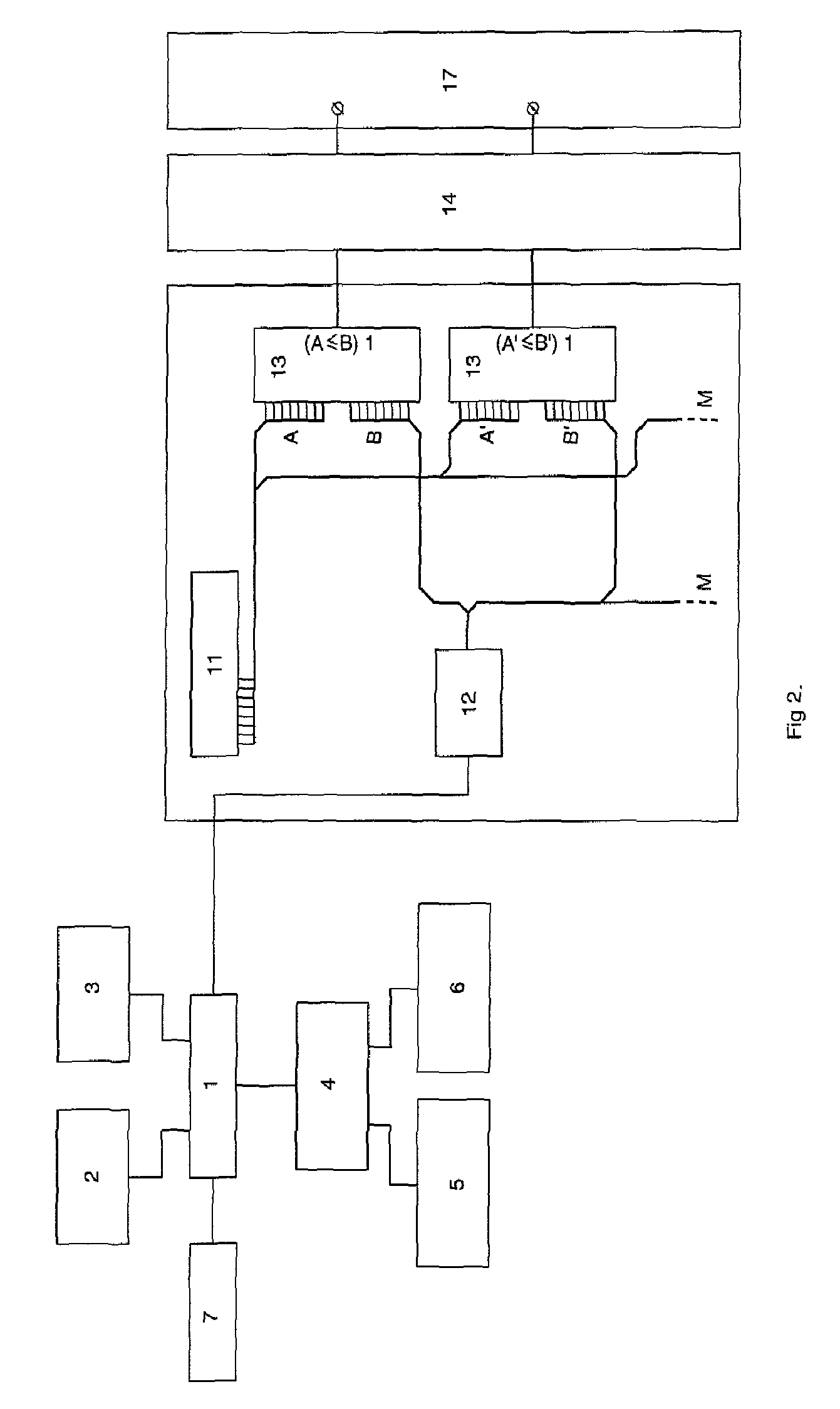
[0010] In the electronic filter device of the invention, a detour is used for converting the analog setting voltages from the digital values. The obvious way would be to use DACs (one for each voltage to be generated), but as mentioned this is undesirable in view of their cost. According to the invention, the digital values are first converted into digitally modulated signals, which are in turn converted into the analog setting voltages. The first part of the conversion circuitry adds some digital components to the device, but these are generally cheap and the digitally modulated signals generated by them are convertible into the analog setting voltages by means of less expensive components than DACs, such as for example resistors and capacitors. As a result of using the detour, each of the analog voltages can be generated by means of its own, dedicated part of the conversion circuitry, there is no longer a need to share different analog voltages on the same line, as is the case in the prior art device on the output of the DACs, nor to use a dynamic switch for connecting the right voltage to the right analog storage location in the dynamic memory. This eliminates the need for a complex refresh-algorithm and an oversized microcontroller.
[0012] Still further, since the first part of the conversion circuitry can be fully digital, integration of the components becomes an option and all or at least some of the components can be integrated into a single chip. This can further reduce the number of separate components in the device and consequently further reduce its price.
[0016] The first part of the conversion circuitry preferably comprises a common register for storing copies of the digital values stored in the memory. In this way the memory is kept separate from the conversion circuitry and unintentional changes to the data can be avoided. The register is preferably common for all comparators, but separate registers for one comparator or groups of comparators are also possible. A further alternative is that the comparators are directly coupled to the memory.

Problems solved by technology

In order to generate these voltages, digitally stored voltage values are converted to analog voltages by means of Digital-to-Analog Convertors (DAC), which are expensive components.
The device known from GB-A-2272341 however has the disadvantage that, in order to keep the voltages in the dynamic memory at the desired level, a continuous refresh-algorithm is needed to connect the DAC-output at regular times to the analog memory locations.
This continuous refreshing of the analog voltages demands a huge portion of the resources of the microcontroller.
This results in the need of an oversized microcontroller, which again increases the cost of the device.

Method used


Image

  • Electronic Filter Device for the Reception of TV Signals
  • Electronic Filter Device for the Reception of TV Signals
  • Electronic Filter Device for the Reception of TV Signals

Examples


Embodiment Construction

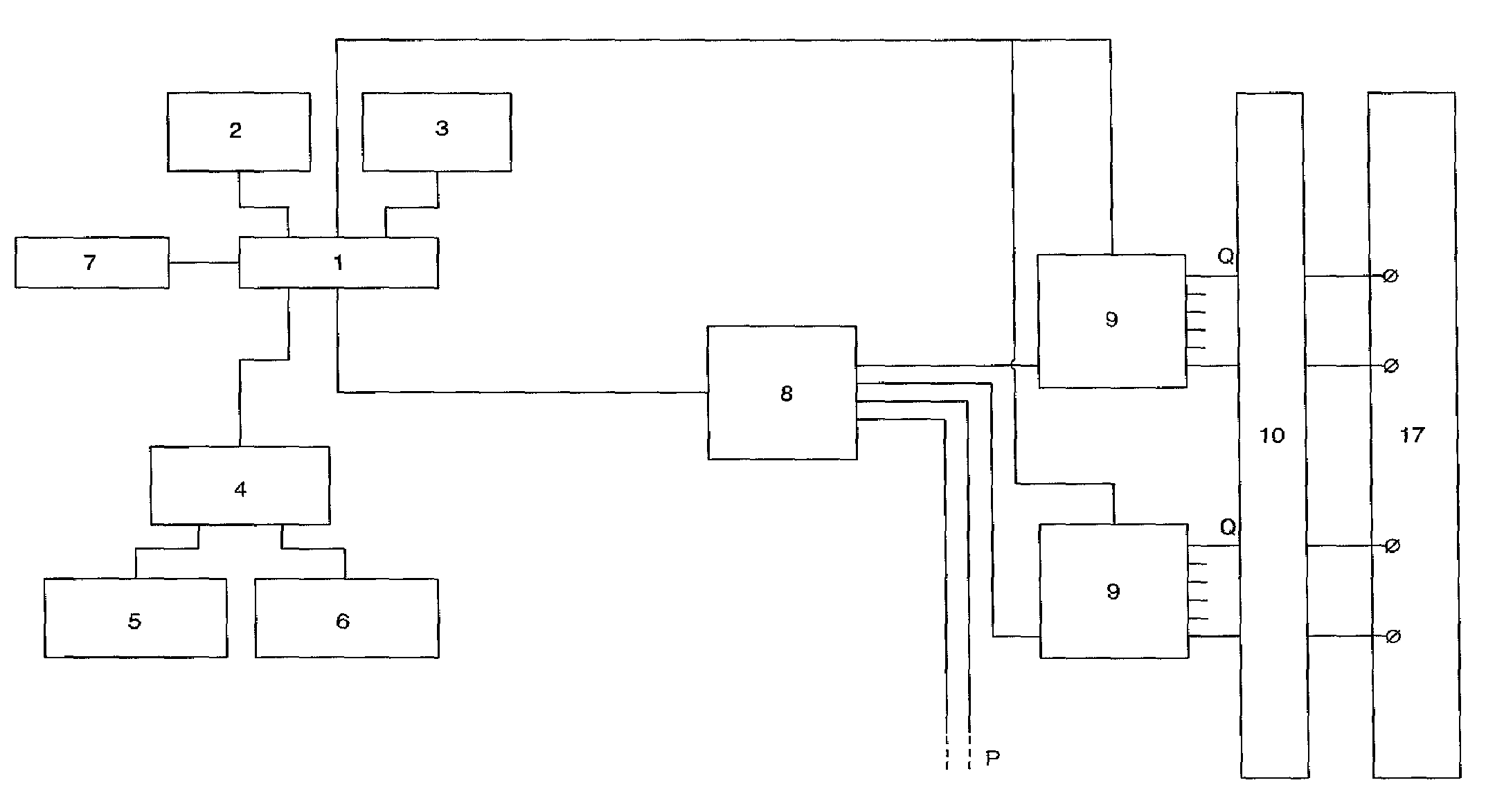
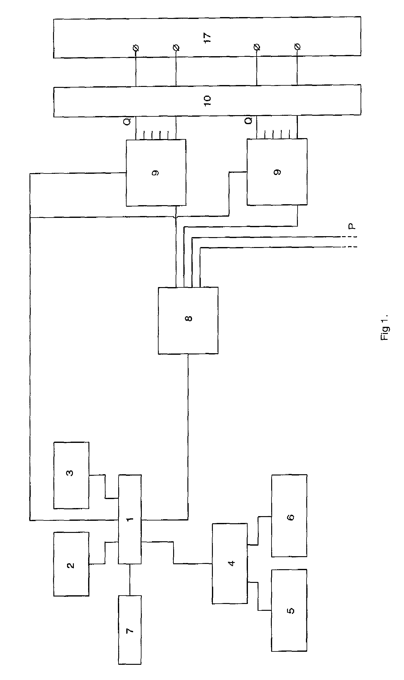
[0025] The prior art device of FIG. 1 is the one which is known from GB-A-2272341. It comprises a microcontroller 1, a non-volatile memory (NVM) 2 for storing factory data and settings made in the field by the installer, a PC-interface 3, for instance for firmware upgrades or changing the settings of the device, a user-interface logic 4 with user-interface input devices 5 and user-interface output devices 6, an RF detection circuit 7 to detect the RF-level needed for an automatic equalization function, a plurality of DACs 8 to generate analog voltages, a plurality of switches 9 (or dynamic multiplexers), and a dynamic memory 10 with “analog storage locations” for storing the analog voltages. The analog voltages are supplied to a bank 17 of voltage outputs and are used for setting frequency determining elements of the RF-circuitry. In FIG. 1, the amount of DACs is P, the amount of dynamic switches is also P and the number of outputs per dynamic switch is Q. A complex dynamic algorith...


PUM


Abstract

An electronic filter device for the reception of TV-signals, comprising a plurality of frequency determining elements settable by means of an analog setting voltage, a memory (2) for storing digital values representative of the analog setting voltages and conversion circuitry (11-14) for converting the digital values into the analog setting voltages. The conversion circuitry comprises a first part (11-13) for generating a digitally modulated signal for each digital value, the digitally modulated signal having a modulated characteristic representative of the digital value, and a second part (14) for converting each of the digitally modulated signals into the analog setting voltages.

Description

TECHNICAL FIELD [0001] The present invention relates to an electronic filter device for the reception of TV-signals according to the preamble of claim 1. BACKGROUND ART [0002] In the 1980s, a fixed filter was commonly used to filter and combine different aerial signals onto 1 cable. Fixed, meaning the installer needed to replace the filter by a totally new filter if frequencies of the channels (or simply the whole application) changed. [0003] In the 1990s, programmable filters came on the market, which could be reprogrammed by the installer on site to serve different frequencies or new applications, so obviating the need for replacement by a new filter. The filter was suitable for all possible applications at that time, so there was no need to develop, produce and store different versions. [0004] One example of such a filter is described in GB-A-2272341. In order to filter the desired TV channels from the incoming signal, the device comprises a plurality of frequency determining ele...

Claims


Application Information

Patent Timeline
IPC IPC(8): H03M1/82
CPCH03J5/0263
Inventor DELEU, STEPHEN
Owner UNITRON
Why Eureka
Eureka Blog
Learn More