Inertial catch for an automatic transfer switch power contactor

Active Publication Date: 2010-11-18
EATON INTELLIGENT POWER LIMITED
View PDF3 Cites 19 Cited by
  • Summary
  • Abstract
  • Description
  • Claims
  • Application Information

AI Technical Summary

Benefits of technology

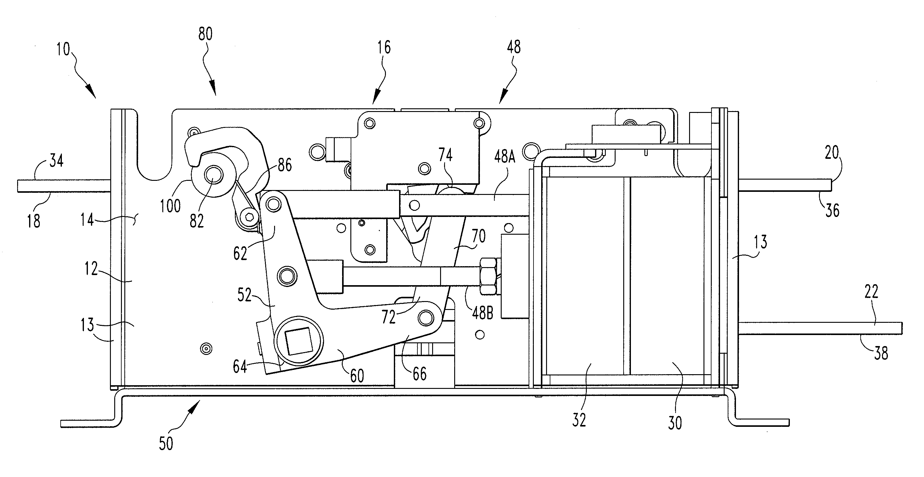
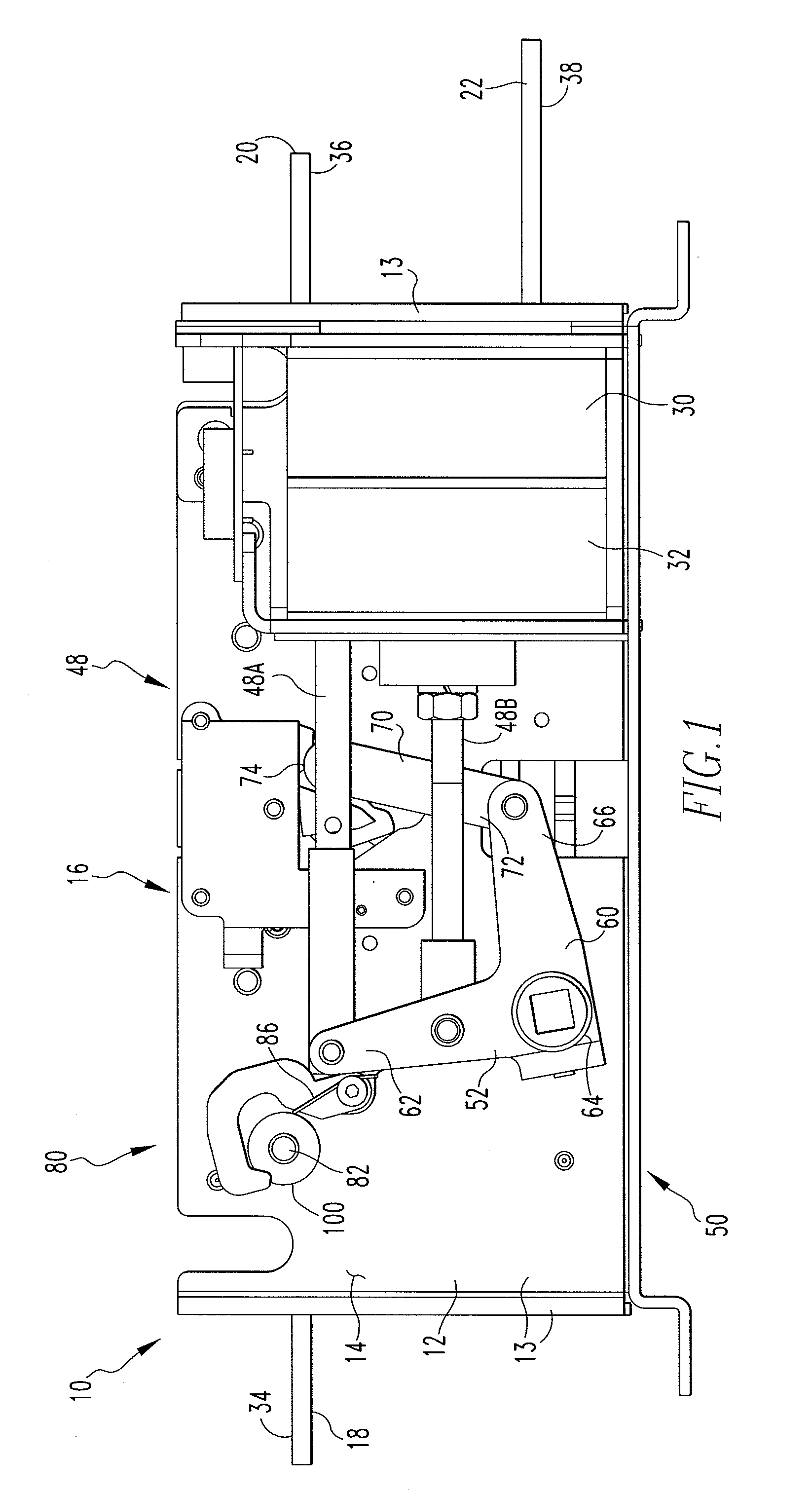
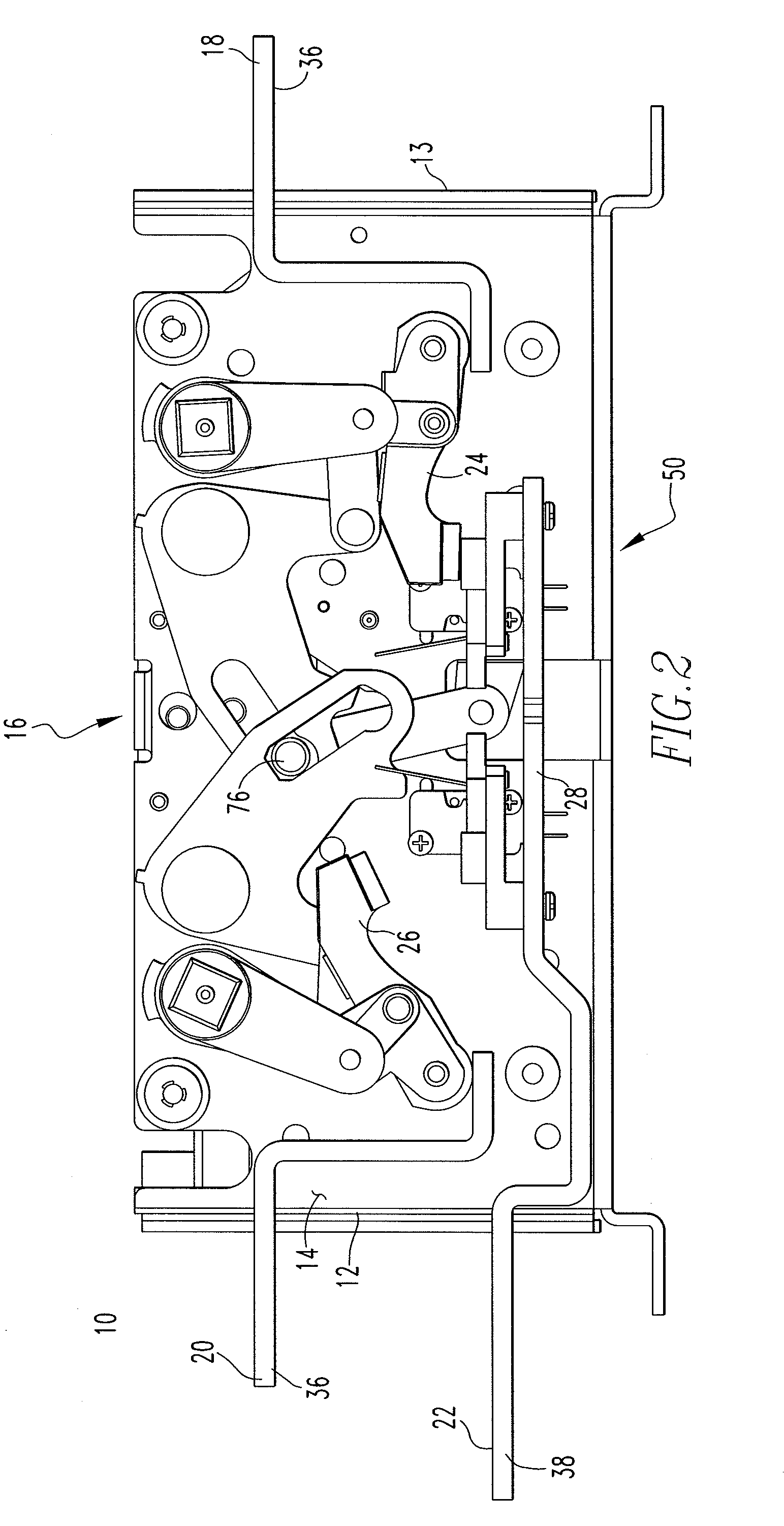
[0011]The concept recited in the claims provides for a catch assembly that is coupled to the operating mechanism of the ATS. The catch assembly is structured to arrest movement within the operating mechanism when the operating mechanism moves at more than the speed for which it was designed. That is, the catch assembly does not engage when the operating mechanism is stationary, or moving at a

Problems solved by technology

That is, the system typically draws power from the primary power source, however, if that source becomes disabled for any period of time, the secondary source is used.
Generally, it is not desirable to have two power sources providing electricity at the

Method used


Image

  • Inertial catch for an automatic transfer switch power contactor
  • Inertial catch for an automatic transfer switch power contactor
  • Inertial catch for an automatic transfer switch power contactor

Examples


Embodiment Construction

[0018]As used herein, “coupled” means a link between two or more elements, whether direct or indirect, so long as a link occurs.

[0019]As used herein, “directly coupled” means that two elements are directly in contact with each other.

[0020]As used herein, “fixedly coupled” or “fixed” means that two components are coupled so as to move as one while maintaining a constant orientation relative to each other.

[0021]As used herein and with reference to electrical components, “engage” shall mean temporarily coupled and allowing for electrical communication.

[0022]As used herein, a “vertex” is the area where two, or more, generally straight components or elements meet or are coupled.

[0023]As is known, any component structured to carry an electrical current is made from a conductive material such as, but not limited to, copper. Components that are not intended to carry a current are made from non-conductive materials and / or are separated from those elements carrying a current by a non-conducti...


PUM


Abstract

A catch assembly coupled to the operating mechanism of the ATS is provided. The catch assembly is structured to arrest movement within the operating mechanism when the operating mechanism moves at more than the speed for which it was designed. That is, the catch assembly does not engage when the operating mechanism is stationary, or moving at a standard speed, i.e. the speed at which the operating mechanism was intended to move. When there is a strong over-current, such as during a withstand test, a magnetic field causes a movable contact to separate from a fixed contact assembly which, in turn, causes the operating mechanism to move at a speed that is faster than the standard speed. The catch assembly is structured to engage and arrest the motion of the operating mechanism when the operating mechanism moves at a speed that is faster than the standard speed.

Description

BACKGROUND OF THE INVENTION[0001]1. Field of the Invention[0002]This invention relates to a bypass isolation open or closed transition automatic transfer switch assembly, commonly called an automatic transfer switch assembly (ATS assembly) and, more specifically, an ATS assembly having a latch assembly structured to resist, and preferably prevent, actuating the switch during a high fault current.[0003]2. Background Information[0004]Certain installations, e.g. hospitals, (hereinafter “the system load”) must have power systems structured to provide an uninterruptable power supply. The primary power source is typically the public power grid and the secondary power source is typically a generator. Both of these sources are structured to provide power over an extended period of time. That is, the system typically draws power from the primary power source, however, if that source becomes disabled for any period of time, the secondary source is used. Generally, it is not desirable to have ...

Claims


Application Information

Patent Timeline
IPC IPC(8): H01H3/20
CPCH01H2300/018H01H1/50
Inventor KRIEGER, JAMES WILLIAMMERCK, PAUL ALANSLEPIAN, ROBERT MICHAELSTAY, AMELIA MARIE
Owner EATON INTELLIGENT POWER LIMITED
Why Eureka
Try Eureka