Full Flow Liquid Filter with Integral Bypass Filtration

a technology of integral bypass and liquid filter, which is applied in the direction of filtration separation, multi-stage water/sewage treatment, separation process, etc., can solve the problems of introducing additional costs and components for automotive assemblers and services, and reducing the overall capacity of full flow and bypass filter media. , the effect of reducing the amount of required storage spa

Active Publication Date: 2010-11-18
MANNHUMMEL PUROLATOR FILTERS
View PDF19 Cites 16 Cited by
  • Summary
  • Abstract
  • Description
  • Claims
  • Application Information

AI Technical Summary

Benefits of technology

[0014]The customer will receive a price benefit resulting from the provision of a less complex system and elimination of extra material from the filtering system. Reduction of required storage space also results from reduced inventories of multiple filters conventionally needed with separate in-line media configurations.

Problems solved by technology

These systems typically introduce additional costs and components for the automotive assembler and service industry to handle and manage.
These sorts of arrangements, however, can reduce the overall capacity for the full flow and bypass filter media.

Method used


Image

  • Full Flow Liquid Filter with Integral Bypass Filtration
  • Full Flow Liquid Filter with Integral Bypass Filtration
  • Full Flow Liquid Filter with Integral Bypass Filtration

Examples


Embodiment Construction

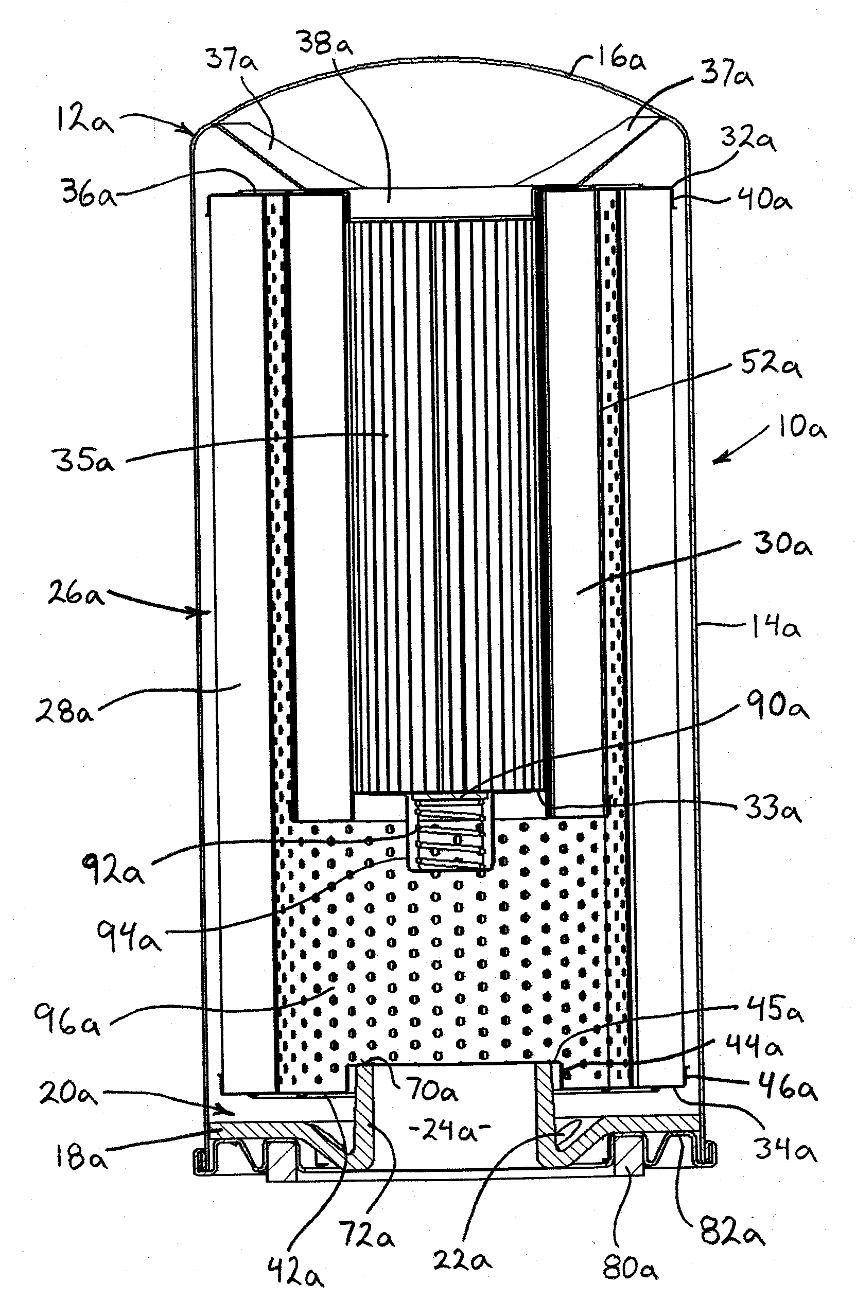
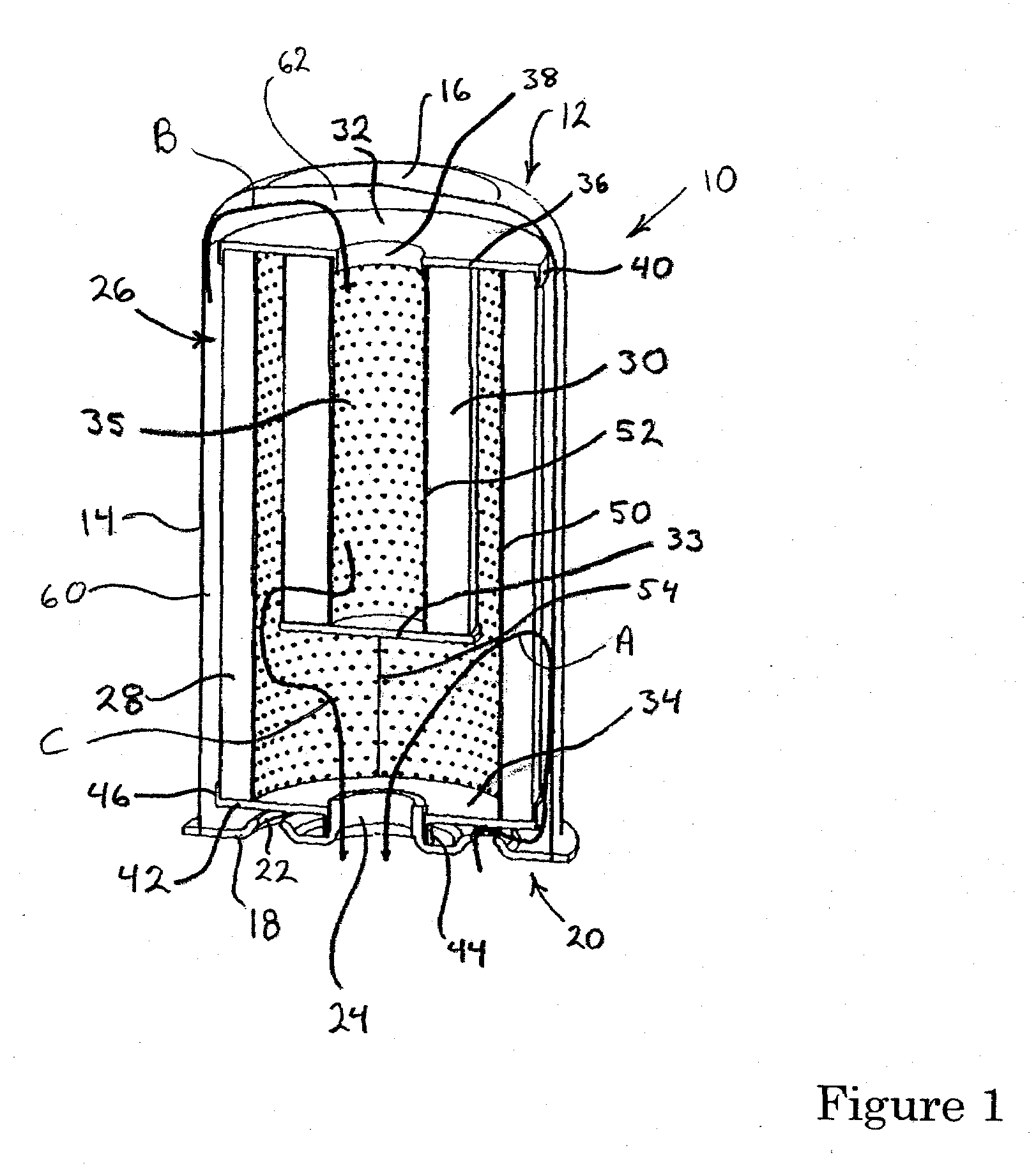
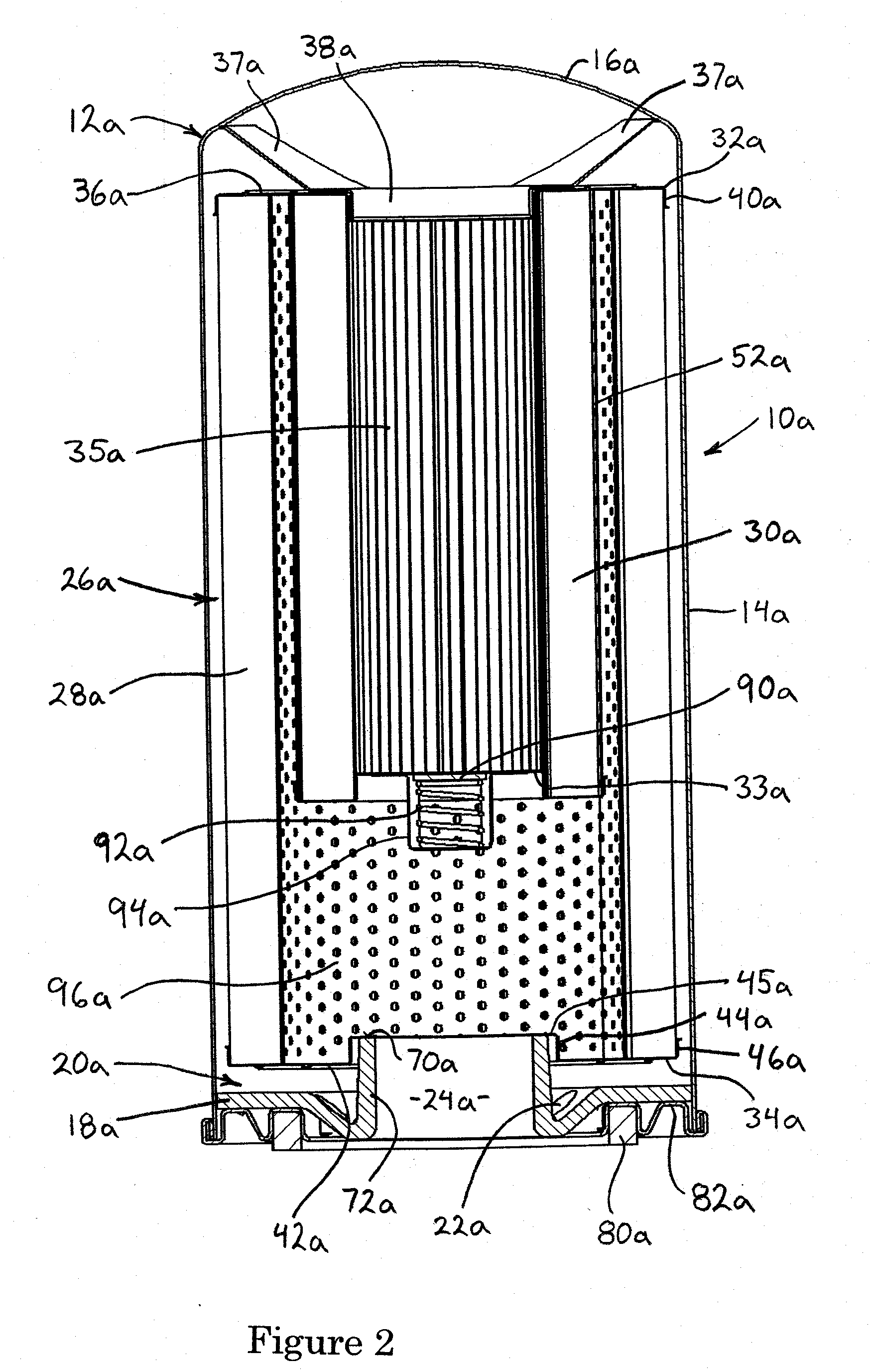
[0017]The liquid filter 10 shown in FIG. 1 includes an outer case 12 composed of an approximately cylindrical side wall 14, a top formed by an end wall 16, and an annular end wall 18 forming part of a bottom assembly 20. The terms “fluid,”“liquid,” and “oil” will be used interchangeably throughout this description, but it should be understood that it is possible to use the filter 10 of the invention in connection with fluids or liquids other than oil when desired. The annular wall 18 is provided with an oil filter discharge opening 24 as well as a hole, slot, perforation, or other such opening 22, or a plurality of holes, slots, perforations, or other such openings, circumferentially surrounding the discharge opening. The discharge opening 24 is typically threaded for connection to a correspondingly threaded fitting attached to or forming part of a vehicle engine, so that oil leaving the filter 10 through the discharge opening enters the engine oil circulating system.

[0018]A filter ...


PUM

PropertyMeasurementUnit
porositiesaaaaaaaaaa
volumeaaaaaaaaaa
pressureaaaaaaaaaa

Abstract

A fluid filter has an outer case with a side wall, a closed first end wall, and a second end wall defining fluid inlet and outlet openings, as well as a filter cartridge received within the outer case. The filter cartridge includes a substantially cylindrical full flow filter element, providing for passage of a major portion of fluid entering the filter, and a substantially cylindrical bypass filter element, providing for passage of a minor portion of fluid entering the filter and disposed radially within and surrounded circumferentially by the full flow filter element. By way of the particular fluid filter configuration disclosed, a simple alternative to known filters having full flow and bypass filters located in common housings is provided.

Description

BACKGROUND OF THE INVENTION[0001]1. Field of the Invention[0002]A simple alternative to known filters having full flow and bypass filters located in common housings is described and claimed.[0003]2. Description of Related Art[0004]Known filter systems for automotive or other applications commonly utilize one of two full flow filter and bypass filter configurations. One such configuration is an arrangement having two separate filtering systems, with a full flow system, which may include more than one filter, depending on flow requirements, and a bypass filter system, which processes only a small percentage of the full fluid volume. In such a configuration, an in-line, series approach is often utilized, with a full flow filter provided downstream of a bypass filter. These systems typically introduce additional costs and components for the automotive assembler and service industry to handle and manage. Vehicle weight is increased as well. U.S. Patent application publication 2008 / 007871...

Claims


Application Information

Patent Timeline
Patent Type & Authority Applications(United States)
IPC IPC(8): B01D29/56
CPCB01D27/103B01D29/114B01D27/144B01D29/117B01D29/54
Inventor BRYSON, THEODORE MICHAELCLINE, L. STEVENEICHLER, CHRISTOPHER
Owner MANNHUMMEL PUROLATOR FILTERS
Why Eureka
Try Eureka