Lid for cup

Inactive Publication Date: 2010-11-18
BOOTH MICHAEL LYLE
View PDF11 Cites 22 Cited by
  • Summary
  • Abstract
  • Description
  • Claims
  • Application Information

AI Technical Summary

Benefits of technology

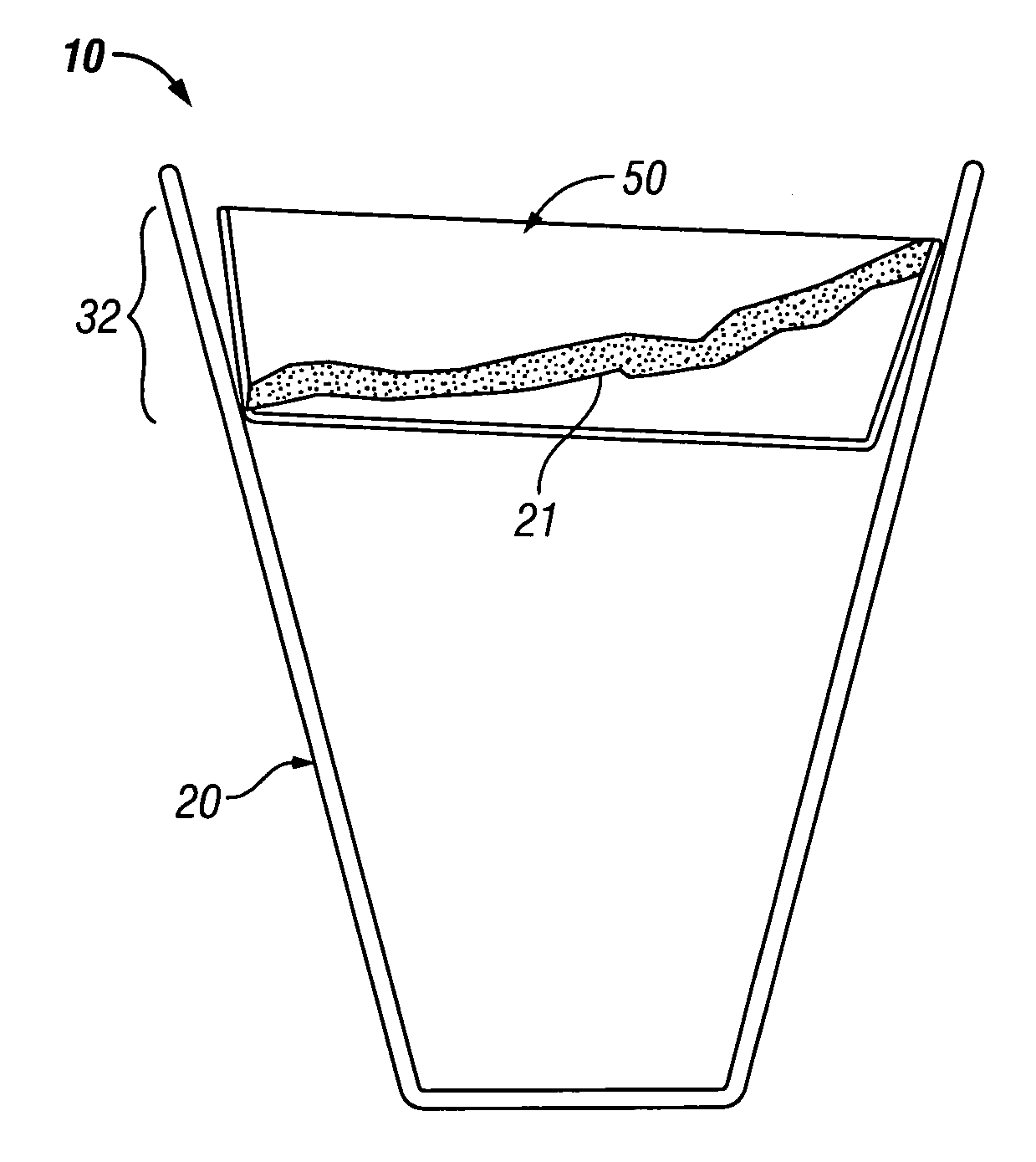
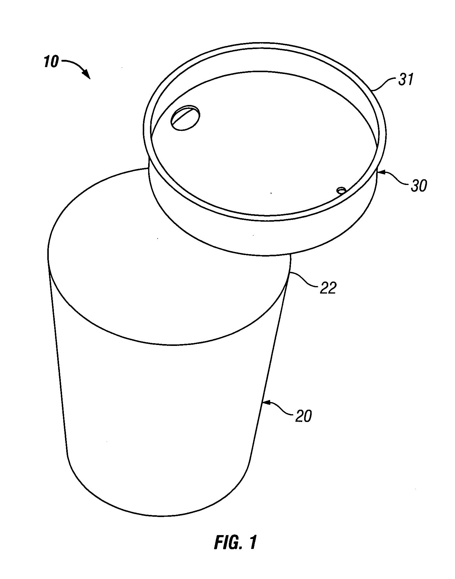
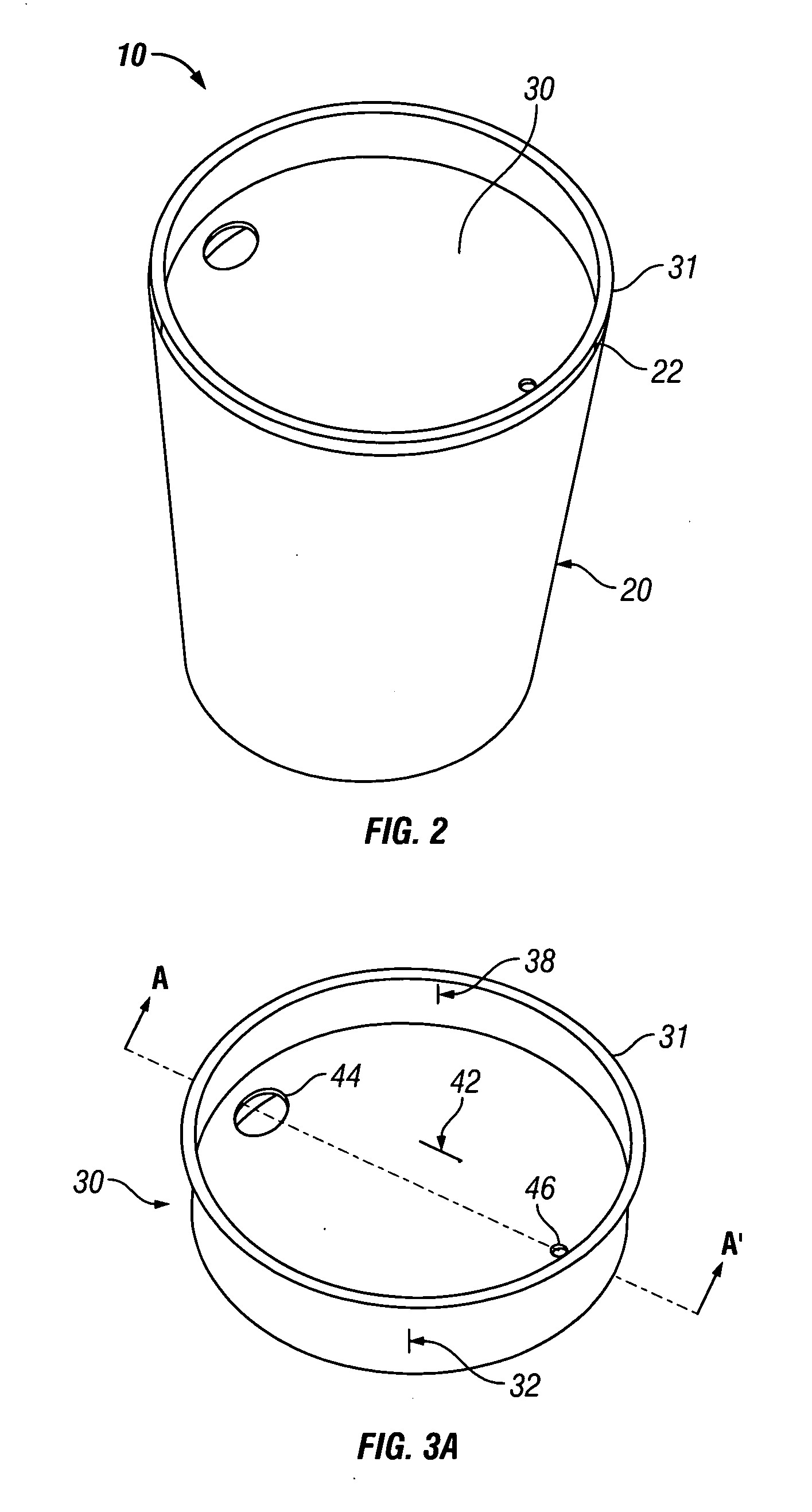
[0012]The present invention has many aspects. In one aspect, the present invention provides a lid for a cup with the lid having an annular wall which, at least in part, comes into engagement with an annular wall of the cup to create a seal preventing fluid flow outwardly therepast. The cup preferably has a frustoconical side wall and the lid has a complementary frustoconical side wall for engagement with the frustoconical side wall of the cup. The cup and lid may be formed from any materials, however, in one particularly preferred embodiment, the cup and lid are both formed from paper, as defined herein, and may preferably be recycled together. Overlapping of the annular frustoconical side wall of the c

Problems solved by technology

When the cup and lid are made from materials from different recycling categories, the disadvantage arises that the container may be rejected for recycling.
Cups which are to receive hot materials such as, for example, hot coffee, suffer from the disadvantage that the cup particularly when made from inexpensive materials such as light plastic or paper, permits the heat from the hot material to be transmitted through the cup making the cup too hot to hold in a user's hand.
A similar disadvantage can occur with cups to hold other materials such as soups, pasta, rice or any other materials which might be hot.
As well, a similar disadvantage arises in respect of cold materials such as, for example, a cold beverage or a cup containing crushed ice where, in that case, the

Method used


Image

  • Lid for cup
  • Lid for cup
  • Lid for cup

Examples


Example

[0076]Reference is made to FIGS. 8 to 10 which show a container formed from a second embodiment of a cup 20′ and a lid 70. The cup 20′ has a construction of a type which is generally known in the art with a frustoconical, tapering outer annular wall 132 having a rolled top rim 22. As seen in FIG. 10, the outer annular wall 132 extends downwardly to a bottom base 136 where the material forming the wall bends upwardly as an inner annular wall 133 which extends upwardly inside the outer annular wall 132 to where the inner annular wall 133 merges with a bottom disc 141 closing the bottom of the cup as a surface 142.

[0077]The lid 70 shown in FIG. 10 has a construction analogous to the construction of the cup 20′. As seen the lid 70 is a frustoconical tapering annular outer wall 32 which carries a rolled top rim 34. The outer annular wall extends downwardly to the bottom base 36 where the material forming the outer annular wall is folded back upon itself and extends upwardly as an inner a...


PUM


Abstract

A lid for a cup includes an annular wall with a top rim and a bottom base. The annular wall is insertable into a cup wherein an exterior face of the annular wall produces a compressive force against an interior face of the cup sufficient to create a seal along a continuous path circumscribing the interior face of the annular wall of the cup.

Description

RELATED APPLICATION[0001]This application is a continuation-in-part of U.S. patent application Ser. No. 12 / 467,562 filed May 18, 2009 and the applicant claims the benefit of 35 U.S.C. 120.SCOPE OF THE INVENTION[0002]The invention relates generally to a lid for a disposable container.BACKGROUND OF THE INVENTION[0003]A dispensing container is typically formed with a cup and a lid that attaches to the rim of the cup. After putting a liquid into the cup, the lid is attached to form a sealed container that resists spillage. The lid typically has an orifice of sufficient area to dispense a product. The orifice is large enough to dispense the product based on the viscosity of the product and consumer preference for product flow rate, yet small enough to reduce spillage from tilting or bumping the container. Common examples of a dispensed liquid product are coffee, tea or a cold beverage.[0004]A lid commonly has a concaved lip that attaches to the cup with a compressive force on the rim. Th...

Claims


Application Information

Patent Timeline
IPC IPC(8): B65D3/06B65D3/22B65D3/26B65D43/02
CPCB65D21/022B65D43/022B65D2543/00046B65D2543/00546B65D2543/00268B65D2543/005B65D2543/00509B65D2543/00092
Inventor BOOTH, MICHAEL LYLE
Owner BOOTH MICHAEL LYLE
Why Eureka
Try Eureka