
System, mechanism, and apparatus for a customizable and extensible distributed rendering api

a distributed rendering and api technology, applied in the field of parallel and distributed graphics programming, can solve the problems of reducing reducing the flexibility of programming, and avoiding the benefits of using a scene-graph style data structure, so as to improve the utility and effectiveness of high-end, hide the complexity of parallel and distributed programming, and improve the effect of flexibility

Inactive Publication Date: 2010-11-18
IBM CORP
View PDF13 Cites 67 Cited by
  • Summary
  • Abstract
  • Description
  • Claims
  • Application Information

AI Technical Summary

Benefits of technology

[0015]The interface enables users to develop their application program using a common and familiar programming paradigm (i.e., the scene graph) in a manner that accommodates handling parallel rendering tasks and rendering environments.
[0017]With the system and methodology of the invention, developers are enabled to: 1) write visualization applications that take better advantage of clusters (in terms of rendering as well as application logic); 2) hide the complexity of parallel and distributed programming; and, 3) minimize the effort to port applications by using familiar interfaces.

Problems solved by technology

Currently, there exists challenges including, but not limited to: the distribution of data across the cluster nodes, the variation in data access times (CPU, GPU, local disk, remote disk), the rendering load balancing across the cluster nodes, and, the programming complexity, flexibility, and extensibility.
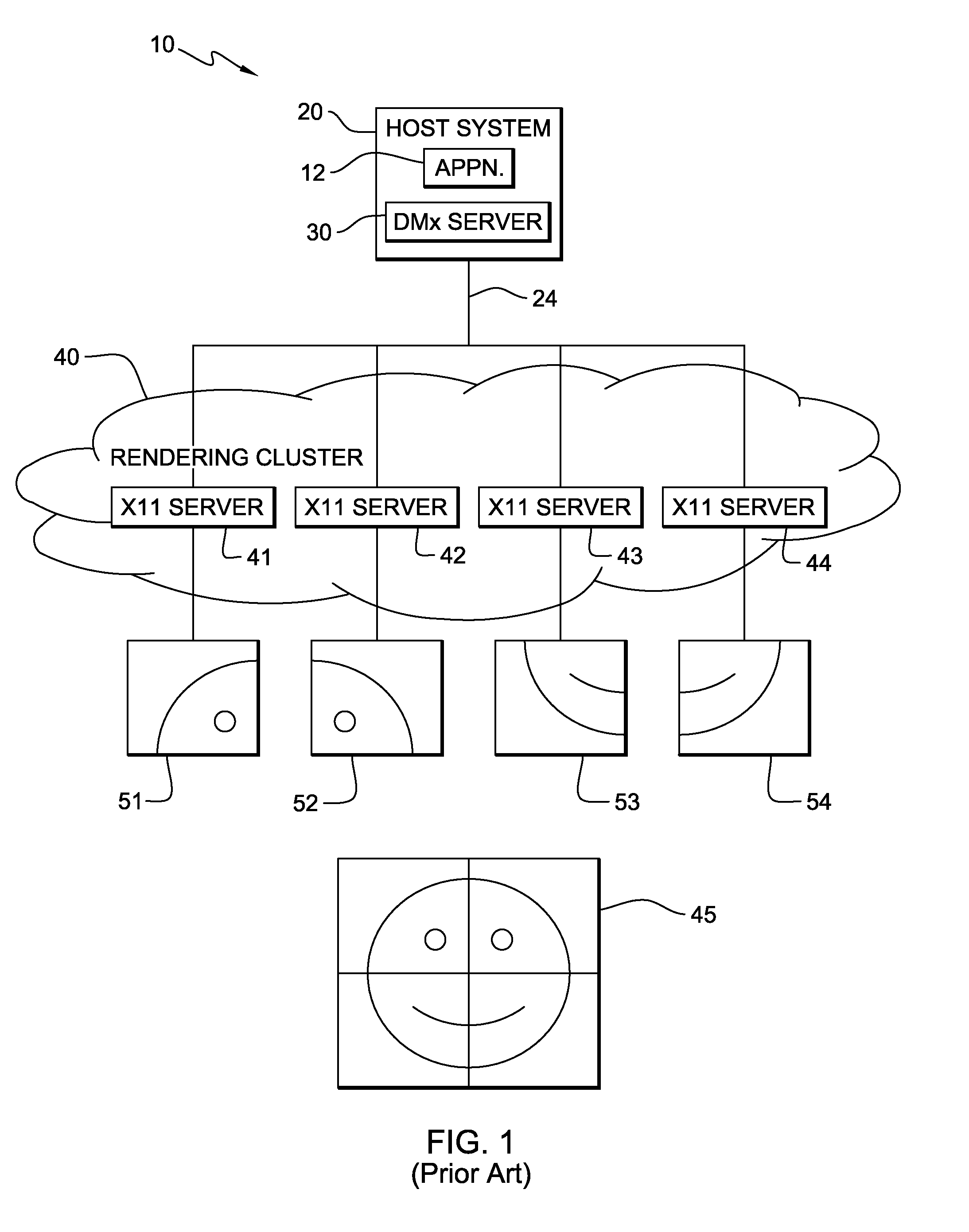
However a major difference, the SGI MPK eschews the use of a scene graph (see, e.g., U.S. Pat. No. 6,933,941) in order to implement several of their optimization techniques and, therefore, forgo the benefits of using a scene-graph style data structure.

Method used


Image

  • System, mechanism, and apparatus for a customizable and extensible distributed rendering api
  • System, mechanism, and apparatus for a customizable and extensible distributed rendering api
  • System, mechanism, and apparatus for a customizable and extensible distributed rendering api

Examples


Embodiment Construction

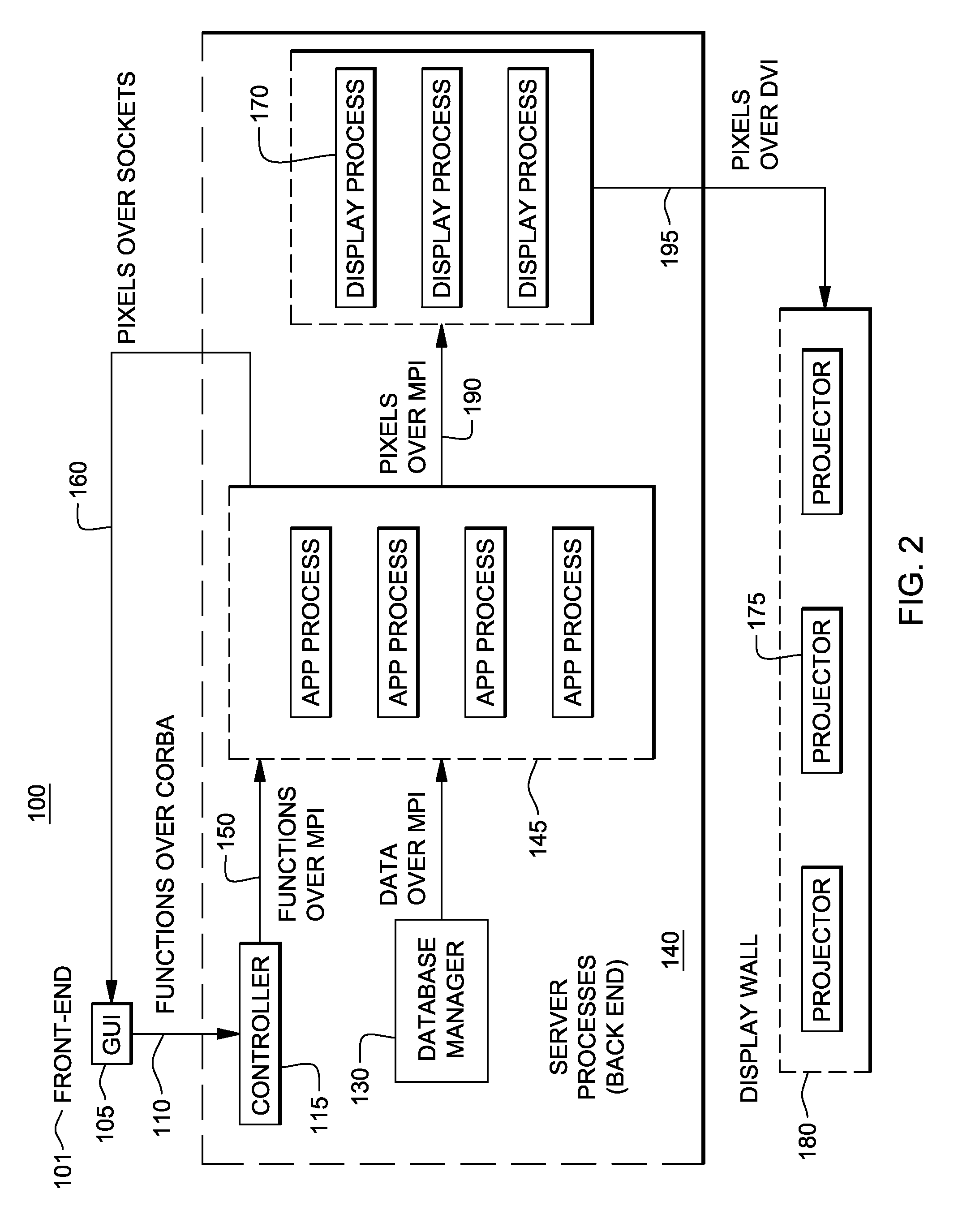
[0038]As shown in FIG. 2, there is depicted a computer system-based design framework 100 enabling users, e.g., developers, to write visualization applications that take better advantage of the aggregate resources of a graphics cluster. The computer system-based design framework 100 provides a distributed parallel visualization toolkit allowing users to write complex graphics and visualization applications with little knowledge of how to parallelize or distribute the application across the graphics cluster.

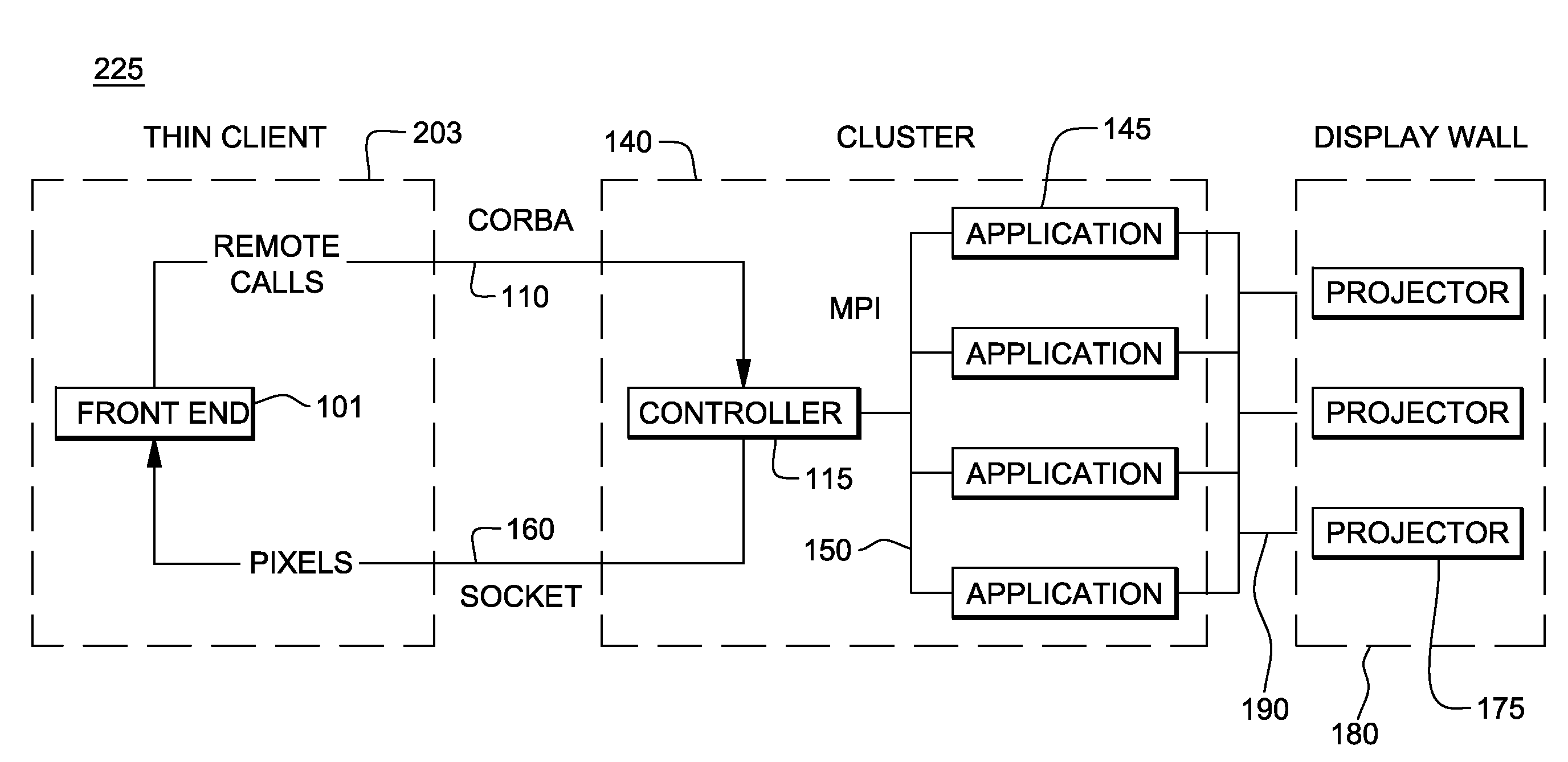
[0039]More specifically, referring to FIG. 2, the design framework 100 includes a system front-end 101 implementing a graphics user interface (GUI) and display device 105 providing an interface for the user that enables access to the cluster controller functions 150 through an object interface, e.g., such as a CORBA® interface (CORBA® is a Trademark of Object Management Group, Inc., www.omg.org). Thus, the front-end 101 may be written in any language supported by the CORBA® Interfa...


PUM


Abstract

A system and method for providing an Application Programming Interface (API) that allows users to write complex graphics and visualization applications with little knowledge of how to parallelize or distribute the application across a graphics cluster. The interface enables users to develop an application program using a common programming paradigm (e.g., scene graph) in a manner that accommodates handling parallel rendering tasks and rendering environments. The visualization applications written by developers take better advantage of the aggregate resources of a cluster. The programming model provided by APT function calls handles scene-graph(s) data in a manner such that the scene and data management are decoupled from the rendering, compositing, and display. As a result, the system and method is not beholden to one particular graphics rendering API (e.g. OpenGL, Direct X, etc.) and provides the ability to switch between these APIs even during runtime.

Description

CROSS-REFERENCES TO RELATED APPLICATIONS[0001]The present invention relates to commonly-owned, co-pending U.S. patent application Ser. No. ______, [Atty. Docket No. YOR920090059US1 (24069)] filed on even date herewith.BACKGROUND OF THE INVENTION[0002]1. Field of the Invention[0003]The present invention relates generally to parallel and distributed graphics programming, and more particularly to a novel visualization toolkit that implements clustering for visualization applications.[0004]2. Description of the Prior Art[0005]With the advent of more powerful and less expensive computing hardware components (e.g. GPUs, CPUs, communication interconnect, displays, etc.), it is becoming increasingly practical, economical, and effective to pool these resources together and harness their aggregate capabilities in the form of a cluster. This philosophy is especially evident in the increasing popularity of graphics clusters or clusters designed specifically for providing high-performance graphi...

Claims


Application Information

Patent Timeline
Patent Type & Authority Applications(United States)
IPC IPC(8): G06F13/14
CPCG06F9/547
Inventor JACKMAN, THOMAS M.KLOSOWSKI, JAMES T.MORRIS, CHRISTOPHER J.
Owner IBM CORP
Learn More