Fiber optical device and method of driving the same

a fiber optic and optical fiber technology, applied in the direction of lasers, electromagnetic transmission, transmission, etc., can solve the problems of optical fiber deterioration phenomenon called photodarkening, disadvantageous photodarkening, and increased light transmission loss in amplification optical fibers

Inactive Publication Date: 2010-11-18
HAMAMATSU PHOTONICS KK
View PDF2 Cites 4 Cited by
  • Summary
  • Abstract
  • Description
  • Claims
  • Application Information

AI Technical Summary

Benefits of technology

[0013]According to the fiber optical device and the method of driving it according to the present invention, the bleaching light source for supplying the bleaching light to the optical fiber is provided in the fiber optical device that includes the amplification optical fiber, the seed light source, and the excitation light source, and the period between the successive first and second output light pulses is divided into the first period

Problems solved by technology

On the other hand, in a pulse operation type fiber optical device, an optical fiber deterioration phenomenon called photodarkening disadvantageously occurs, resulting from the supply of excitation light to the amplification opti

Method used


Image

  • Fiber optical device and method of driving the same
  • Fiber optical device and method of driving the same
  • Fiber optical device and method of driving the same

Examples


Embodiment Construction

[0021]Preferred embodiments of a fiber optical device of the present invention and a method of driving such a fiber optical device will be described in detail below with reference to the accompanying drawings. In the description of the drawings, the same elements will be denoted by the same reference symbols, and overlapping description will be omitted. The dimensional ratios in the drawings do not always agree with those in the description.

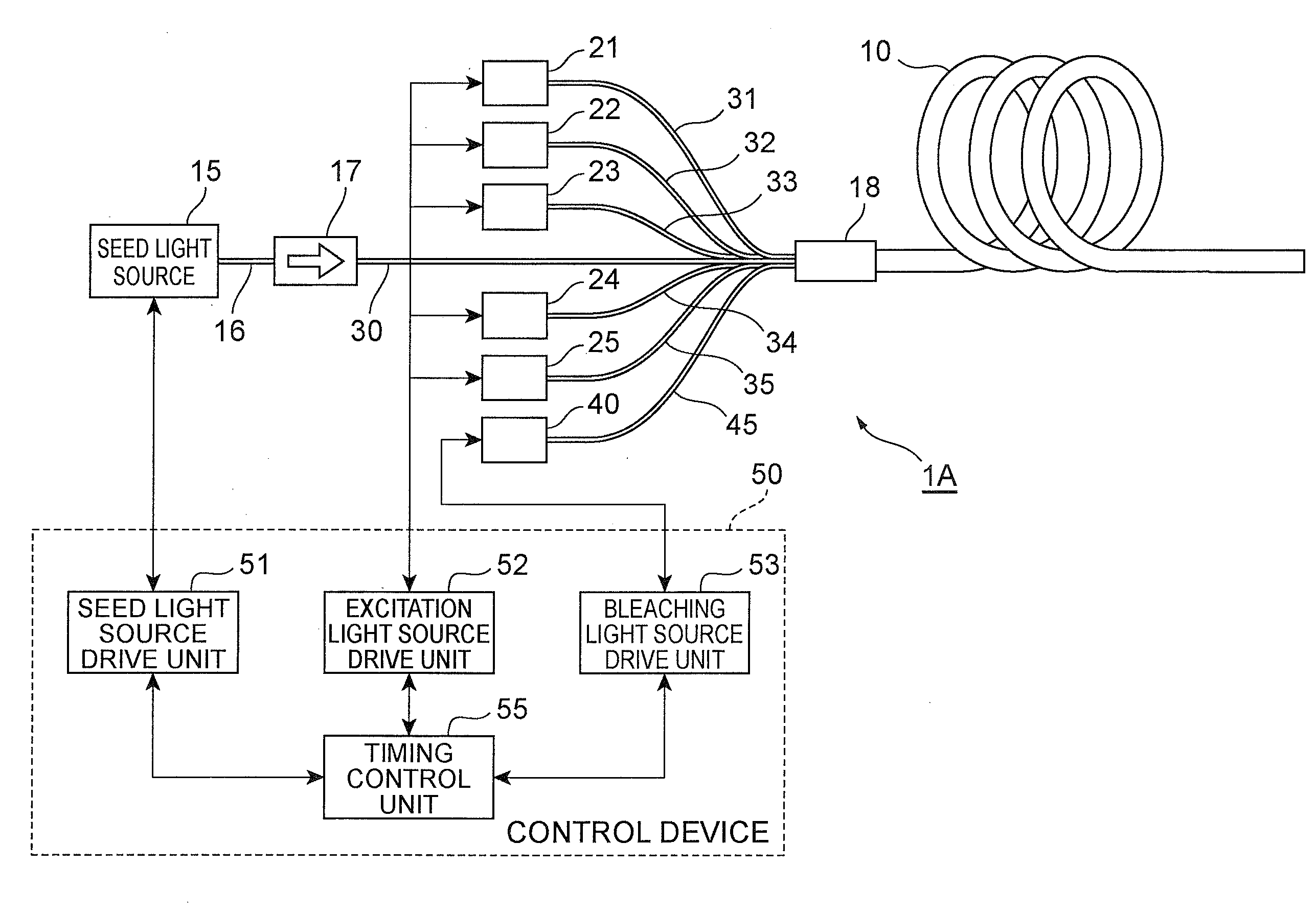
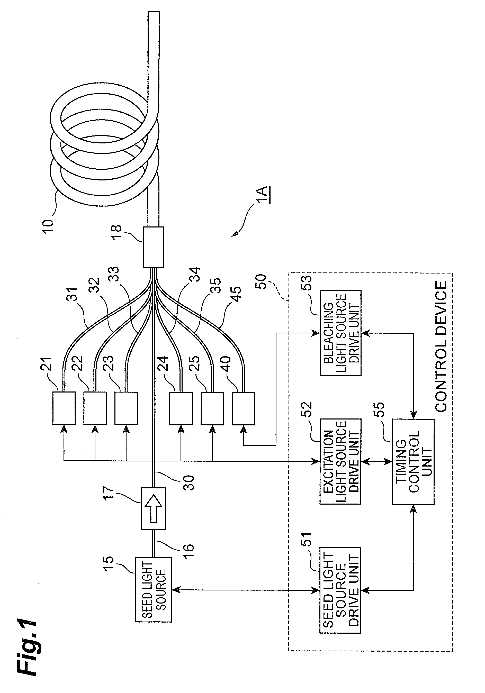
[0022]FIG. 1 is a diagram showing a configuration of an embodiment of a fiber optical device of the present invention. The fiber optical device 1A of this embodiment is provided with an amplification optical fiber 10, a seed light source 15, excitation light sources 21 to 25, and a bleaching light source 40, and serves as a light source device that amplifies pulse seed light supplied from the seed light source 15 in the amplification optical fiber 10 and that outputs the amplified light as an output light pulse.

[0023]The amplification optical fib...


PUM


Abstract

A fiber optical device 1A includes an amplification optical fiber 10, a seed light source 15 for supplying pulse seed light to the optical fiber 10, excitation light sources 21 to 25 for supplying excitation light, a bleaching light source 40 for supplying bleaching light for reducing a light transmission loss caused by photodarkening, and a control device 50 that controls the operations of individual portions. The control device 50 divides a period between a first output light pulse and a succeeding second output light pulse into a first period which includes a time point immediately after the output of the first output light pulse and during which the population inversion is unsaturated, and a second period which includes a time point immediately before the output of the second output light pulse, and, to the optical fiber 10, supplies the bleaching light in the first period and supplies the excitation light in the second period. Thus, it is possible to provide a fiber optical device and the method of driving it that can suitably restore the characteristics of the amplification optical fiber by photobleaching.

Description

TECHNICAL FIELD[0001]The present invention relates to a fiber optical device that uses an amplification optical fiber having a core containing a laser active substance and to a method of driving such a fiber optical device.BACKGROUND ART[0002]As an optical device such as a laser device or an optical amplification device, a fiber optical device is known that uses an amplification optical fiber having a laser active substance such as Yb added thereto. In this type of optical device, with the active substance excited by supplying excitation light (for example, light with a wavelength of 975 nm) to the amplification optical fiber, seed light (light to be amplified) is input to the optical fiber, and thus the seed light is amplified by induced emission and the resulting light is output as output light from the optical fiber. When the optical device is configured as a laser device, a resonator is provided for the amplification optical fiber, and the amplified light performs lasing within ...

Claims


Application Information

Patent Timeline
IPC IPC(8): H01S3/113H01S3/067H01S3/091
CPCH01S3/0014H01S3/06754H01S3/094076H01S3/1618H01S3/09415H01S3/10015H01S3/09408H01S3/1001
Inventor YAMAURA, HITOSHISEKIGUCHI, HIROSHI
Owner HAMAMATSU PHOTONICS KK
Why Eureka
Try Eureka