Start-up circuit for power converters with wide input voltage range

a power converter and input voltage range technology, applied in the direction of power conversion systems, electrical apparatus, etc., can solve the problems of monotonic increase of power losses in the charging resistor under steady state conditions of this conventional technique, limiting the conventional technique to being usable only in power converters with relatively narrow input voltage ranges, etc., to achieve a wide input voltage range

Active Publication Date: 2010-11-18
MURATA POWER SOLUTIONS
View PDF7 Cites 18 Cited by
  • Summary
  • Abstract
  • Description
  • Claims
  • Application Information

AI Technical Summary

Benefits of technology

[0017]To overcome the problems described above, preferred embodiments of the present invention provide a more efficient start-up circuit for power converters with wide input voltage range.

Problems solved by technology

One drawback of this conventional technique is that the capacitance value and the physical size of the energy storage capacitor must both be relatively large to provide sufficient energy for the startup process to commence.
Another drawback of this conventional technique is that the current charging the energy storage capacitor, and consequently the start-up time, depends on the input voltage, which limits this conventional technique to being usable only in power converters with relatively narrow input voltage ranges.
Moreover, power losses in the charging resistor under steady state conditions of this conventional technique will increase monotonically with the input voltage.
However, this conventional technique does not fully eliminate start-up power dissipation.
However, if the input DC voltage has a wide range, then power dissipation in resistor 106 cannot be neglected because power dissipation increases directly proportional to the square of the input DC voltage.
Accordingly, the above conventional technique is undesirable because it requires the capacitor 105 to be relatively expensive, large value, and physical size, because it does not have a fixed start-up time, and the power dissipation losses under steady state conditions limit start-up circuits based on energy storage capacitors to only those that have a relatively narrow input voltage range.
However, if the input voltage range is wide, the power dissipation P requires a physically larger resistor size, thus causing overall efficiency deterioration and an increasing no-load current.
The above example demonstrates that the conventional start-up circuit 200 of FIG. 2 is efficient enough in a relatively narrow input voltage range and is not efficient in a wide input voltage range.

Method used


Image

  • Start-up circuit for power converters with wide input voltage range
  • Start-up circuit for power converters with wide input voltage range
  • Start-up circuit for power converters with wide input voltage range

Examples


Embodiment Construction

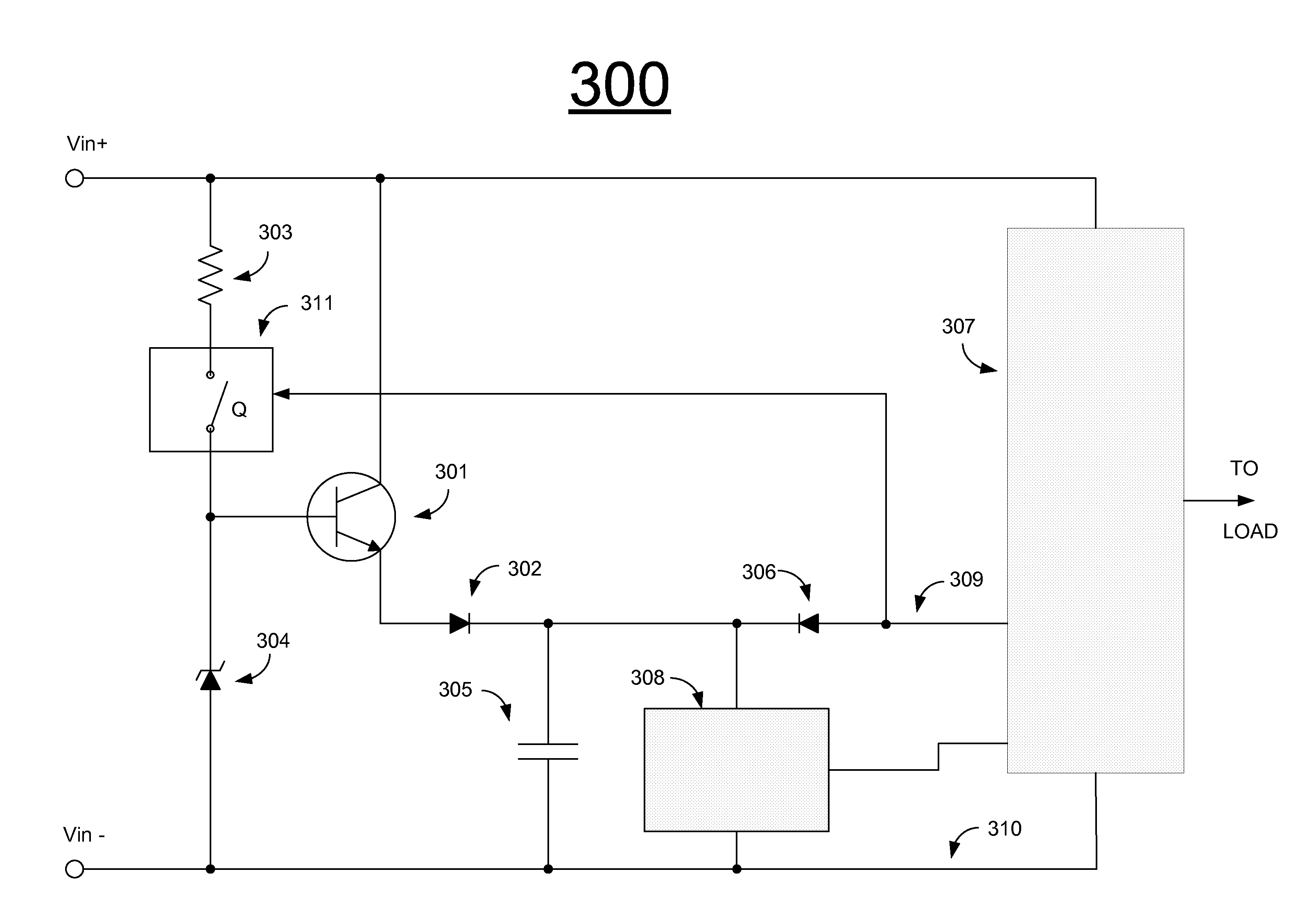
[0026]FIG. 3 shows a start-up circuit 300 according to the first preferred embodiment of the present invention that includes start-up transistor 301, first diode 302, resistor 303, zener diode 304, capacitor 305, second diode 306, power converter 307 with control circuit 308 and with auxiliary output terminals 309, 310, and switch Q with control circuit 311. In contrast to FIG. 2, FIG. 3 includes a switch Q that is controlled by the voltage across auxiliary output terminals 309, 310 and that is connected in series with resistor 303.

[0027]The start-up circuit 300 in FIG. 3 operates in the following manner. After the input voltage Vin is applied across terminals Vin+, Vin−, zener diode 304 is activated through resistor 303 and switch Q that is initially ON. Transistor 301 supplies a start-up voltage at the input of the control circuit 308 and across filter capacitor 305 equal to the zener voltage Vz of the zener diode 304 minus the combined voltage drops of transistor 301 and first di...


PUM


Abstract

A start-up circuit includes a switching-device control circuit arranged to receive an input voltage and to provide a switching-device control signal, a switching device arranged to be controlled by the switching-device control signal and to provide a start-up signal, a power-converter control circuit arranged to receive the start-up signal and to provide a power-converter control signal, and a power converter arranged to receive the power-converter control signal and to provide an auxiliary output signal. The switching control circuit is arranged to receive the auxiliary output signal such that, when the auxiliary output signal reaches a predetermined level, the switching-device control circuit stops providing the switching-device control signal.

Description

BACKGROUND OF THE INVENTION[0001]1. Field of the Invention[0002]The present invention relates to power converters. More specifically, the present invention relates to start-up circuits that provide start-up voltage to a control system of a power converter during a power-up process when the output voltage rises from zero to a nominal level.[0003]2. Description of the Related Art[0004]According to one conventional start-up technique, an energy storage capacitor placed across the input terminals of a control circuit is charged up to the start-up level through a resistor connected to the input voltage. One drawback of this conventional technique is that the capacitance value and the physical size of the energy storage capacitor must both be relatively large to provide sufficient energy for the startup process to commence. An electrolytic or other polarized type capacitor is typically used for this purpose. Another drawback of this conventional technique is that the current charging the ...

Claims


Application Information

Patent Timeline
Patent Type & Authority Applications(United States)
IPC IPC(8): H02M1/00
CPCH02M2001/0006H02M1/36H02M1/0006
Inventor ASINOVSKI, ALEXANDERGONSALVES, JOSEPH
Owner MURATA POWER SOLUTIONS
Why Eureka
Try Eureka