Synchronous rectifying circuit and implementing method

A synchronous rectification and circuit technology, applied in the direction of electrical components, output power conversion devices, etc., can solve the problems of high cost of control IC, unsuitable topology, difficult control signal acquisition of converters, etc., to achieve wide range of load current variation, The effect of a wide input voltage range

Active Publication Date: 2014-04-02
天津航空机电有限公司
View PDF3 Cites 13 Cited by
  • Summary
  • Abstract
  • Description
  • Claims
  • Application Information

AI Technical Summary

Problems solved by technology

[0004] The main disadvantage of synchronous rectification in the voltage-type self-driven mode is that the driving voltage of the SR is proportional to the input voltage of the switching converter. When the input voltage range is wide, it is difficult to drive the SR safely and reliably in the entire voltage range; the current The main disadvantage of the self-driven synchronous rectification method is that it is difficult for the converter to obtain the control signal when it is light-loaded or no-loaded; Some topologies where the secondary side loses the duty cycle are not suitable; the synchronous rectification of the control IC method solves some of the above-mentioned shortcomings due to the integration of the internal circuit, but the cost of the control IC is relatively high

Method used


Image

  • Synchronous rectifying circuit and implementing method

Examples


Embodiment Construction

[0020] The technical solution created by the present invention is described in detail in conjunction with the accompanying drawings and specific embodiments.

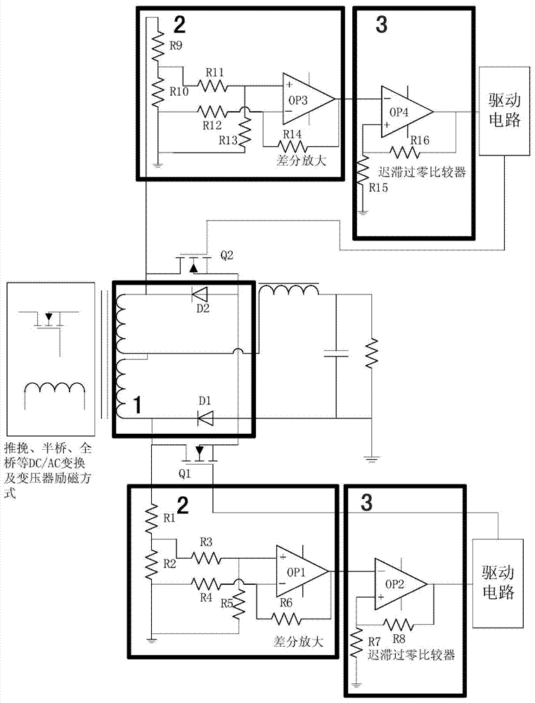
[0021] A synchronous rectification circuit, including two MOSFETs respectively connected to the opposite ends of the full-wave rectification winding of the transformer, the first MOSFET and the second MOSFET are symmetrically connected to a group of opposite ends of the full-wave rectification winding of the transformer, and the first MOSFET and The source of the second MOSFET is connected to the ground of the output terminal of the switching converter; the source of the first MOSFET is connected to the anode of the first diode, and the drain is connected to the cathode of the first diode; the source of the second MOSFET is connected to the second The anode of the diode is connected to the drain of the cathode of the second diode. The drain of the first MOSFET is connected in series with the first resistor, the third re...


PUM


Abstract

The invention provides a synchronous rectifying circuit which comprises two MOSFETs (Metal-Oxide-Semiconductor Field Effect Transistor) respectively connected to the different polarity ends of one transformer full-wave rectification winding. A diode is connected in parallel between a source electrode and a drain electrode of each MOSFET; after being connected in series with a divider resistance, the drain electrode of each MOSFET is connected with the input end of a differential amplification circuit; the output end of the differential amplification circuit is connected with the input end of a comparison circuit; an output of the comparison circuit is connected with a driving circuit of the MOSFETs; an output of the driving circuit is connected with grid electrodes of the MOSFETs; after being connected in series, the different polarity ends of the other transformer full-wave rectification winding are connected with an output filter inductance; the output filter inductance is connected in series with a power supply load resistance. The synchronous rectifying circuit has the advantages of simplicity and practicality, does not depend on a primary control signal during operation, has the obvious advantage for a half-bridge topology, a phase-shifted full-bridge topology and the like which lose the duty ratio, can allow an input voltage to have a wider range, can be suitable for the place with large load variation and is low in cost.

Description

technical field [0001] The invention relates to synchronous rectification technology, in particular to a synchronous rectification circuit and a realization method. Background technique [0002] As a switching converter, there must be a rectification link at the output end for better DC output. As the main switching device of the output circuit, a diode is usually used (using its unidirectional conductivity). It can be understood as a switch that turns on as long as there is sufficient forward voltage without the need for additional control circuits. However, its conduction voltage drop is relatively high, and the conduction voltage drop of a fast recovery diode or an ultra-fast recovery diode can reach 1.0-1.2V. Even if a low-drop Schottky diode is used, the voltage drop is about 0.6V. This voltage drop generates power dissipation, and the rectifier diode is a fixed voltage drop device. The loss of such devices is very large in the working environment of low voltage and ...

Claims


Application Information

Patent Timeline
Patent Type & Authority Applications(China)
IPC IPC(8): H02M1/08
Inventor 张承良尚艳强
Owner 天津航空机电有限公司
Why Eureka
Try Eureka