Wave trough control circuit and wave trough control method

A technology for controlling circuits and wave troughs, which is applied in the direction of control/regulation systems, electrical components, and adjustment of electrical variables, etc., can solve problems such as difficult design of EMI circuits, large output ripples, and large range of operating frequency changes of switching tubes. Effect of Design and Optimization, Elimination of Output Ripple, Reduction of Full Load Operating Frequency Range

Active Publication Date: 2018-02-27
MORNSUN GUANGZHOU SCI & TECH +1
View PDF5 Cites 13 Cited by
  • Summary
  • Abstract
  • Description
  • Claims
  • Application Information

AI Technical Summary

Problems solved by technology

Assuming two common prototypes (the first input is 100VDC-400VDC, the reflected voltage is 100V, the second input is 9VDC-36VDC, and the reflected voltage is 10VDC), ignoring the small part of the resonance time in the critical mode, according to the formula Vin*D=Voff*(1-D), L*Ipk=Vin*D*T, Pin=1 / 2*L*Ipk 2 *f, assuming that the efficiency under high and low pressure is the same, it can be concluded that the operating frequency of the first prototype under high pressure is 2.56 times that under low pressure, and the operating frequency of the second prototype under high pressure is 2.73 times under low pressure , so the operating frequency of the switching tube in the traditional scheme varies greatly, and the EMI circuit is difficult to design
Moreover, the operating frequency will be very high under high input voltage, resulting in very low efficiency under high input voltage, so it can only be used for applications with a relatively narrow input voltage range.
[0008] The second defect of the valley control scheme of the traditional control chip is: when the FB voltage corresponding to the load is just near the gear, assuming that the FB voltage reaches the second gear, the resonance valley number of the MOS transistor TR1 will be at the 4th gear. Constantly switch between the first trough and the third trough, because that point is a critical value
The usual idea is to add a hysteresis to make the judgment of the critical point more stable, but under this condition even if the hysteresis is increased, it will cause valley switching, because when the working state changes from a condition with a large number of troughs to a condition with a small number of troughs After the state (FB pin voltage from low to high), the operating frequency of the switch tube is equivalent to a sudden change, and the peak current cannot change immediately, so according to the energy formula Pin=1 / 2*L*Ipk 2 *f can know that the input energy will suddenly increase, which will inevitably cause an increase in the output voltage, and the increase in the output voltage will inevitably cause a decrease in the voltage of the FB pin, so it will jump back to the one with more valleys. original state
The magnitude of the FB pin voltage change will exceed the amplitude of the hysteresis. The fundamental reason is that the switching trough will inevitably cause a sudden change in energy, and the sudden change in energy will further cause a sudden change in the voltage of the FB pin, thus forming an oscillation.
In such an oscillating situation, the output ripple will become very large, especially in DCDC applications. Since the conventional ripple requirement of most products is only about 50mV, when the output capacitance is small, the traditional solution valley switching The time ripple reaches 100-200mV, so the traditional solution is difficult to use in the field of DCDC micropower

Method used


Image

  • Wave trough control circuit and wave trough control method
  • Wave trough control circuit and wave trough control method
  • Wave trough control circuit and wave trough control method

Examples


Embodiment 1

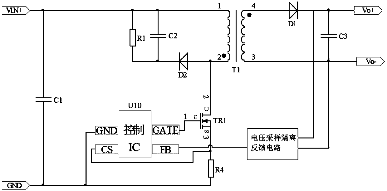
[0036] Figure 4 It is the circuit schematic diagram of the flyback converter of the present invention. The flyback converter includes a transformer T1, a primary side circuit, a secondary side circuit and a control circuit. The primary side circuit includes a filter capacitor C1, a main power circuit, a clamping circuit, and a current sampling circuit. And the voltage divider circuit, the main power circuit is formed by connecting the primary winding of the transformer T1 and the main switching tube TR1 (the main switching tube is a MOS tube, which may also be referred to as MOS tube TR1 below). The clamping module is formed by connecting a resistor R1, a capacitor C2 and a diode D2. The current sampling circuit is formed by connecting resistor R4. The secondary circuit is composed of the secondary winding of the transformer T1, the diode D1, and the capacitor C3. The control circuit is composed of a control chip U1 and a voltage sampling isolation feedback circuit. The con...

Embodiment 2

[0047] Figure 8 It is the circuit schematic diagram of the valley control circuit of the second embodiment of the present invention applied in the flyback converter. Compared with the first embodiment, the main MOS transistor TR1 of the flyback converter and the resistor R4 of the current sampling circuit are used in the second embodiment It is integrated into the chip of the control chip U1', which simplifies the peripheral parameters. The control chip U1' includes UVP pins, GND pins, DRIN pins and FB pins. The UVP pins are input voltage detection pins, which are used to detect the gears of the input voltage to determine which valleys to open and do Undervoltage protection; the GND pin is the reference ground pin of the chip; the DRIN pin is the drain pin of the switch tube, which is used to sample the waveform of the drain of the built-in MOS transistor TR1, and provide it to the valley control circuit to count the number of valleys ; and as the drain terminal of the built...


PUM


Abstract

The invention provides a wave trough control circuit and a wave trough control method. By means of the wave trough control method and the wave trough control circuit, the input voltage range can be widened without wave trough switching oscillations. The wave trough control circuit comprises a current detection circuit, a secondary side feedback circuit, a drive output circuit, an input voltage detection circuit and a waveform detection circuit, wherein the current detection circuit is used for detecting the peak current on the primary side of the source electrode of a switch tube so as to control the switch-on time of the switch tube; the secondary side feedback circuit is used for receiving a voltage signal which is fed back by a voltage sampling isolation feedback circuit and used for reflecting the size of a load; the drive output circuit is used for outputting a drive signal to the switch tube; the input voltage detection circuit is used for detecting the input voltage of a flybackconverter so as to allow the wave trough control circuit to judge what number of the wave trough, at which the switch tube is turned on, in the switching period according to the tap position of the voltage; the waveform detection circuit is used for sampling the waveform at the drain electrode of the switch tube and counting the wave troughs.

Description

technical field [0001] The invention relates to the field of switching converters, a flyback converter working in a discontinuous mode, in particular to a valley control method and a valley control circuit of the flyback converter in DCDC applications. Background technique [0002] With the development of science and technology, there are more and more electrical equipment, instruments, and electronic products, and the demand for switching power supplies is also increasing. The emergence of some portable electronic products has increased the demand for switching power supplies in the micro-power segment. [0003] At present, the switching power supply scheme used in the micro-power segment is mainly the flyback circuit, because it has a series of characteristics such as low cost, simple and reliable circuit, and mature application. There are two working modes of the flyback circuit, one is continuous mode (CCM) and the other is discontinuous mode (DCM). Generally, the conti...

Claims


Application Information

Patent Timeline
Patent Type & Authority Applications(China)
IPC IPC(8): H02M3/335
CPCH02M3/33523Y02B70/10
Inventor 赵永宁唐盛斌
Owner MORNSUN GUANGZHOU SCI & TECH
Why Eureka
Try Eureka