Valley control circuit and valley control method
A control circuit and wave trough technology, which is applied in the direction of control/regulation system, electrical components, and adjustment of electrical variables, can solve the problems of large output ripple, large range of switching tube operating frequency, and difficult design of EMI circuits, etc., to eliminate output Ripple, reduced operating frequency range at full load, beneficial design and optimization effects
- Summary
- Abstract
- Description
- Claims
- Application Information
AI Technical Summary
Problems solved by technology
Method used
Image
Examples
Embodiment 1
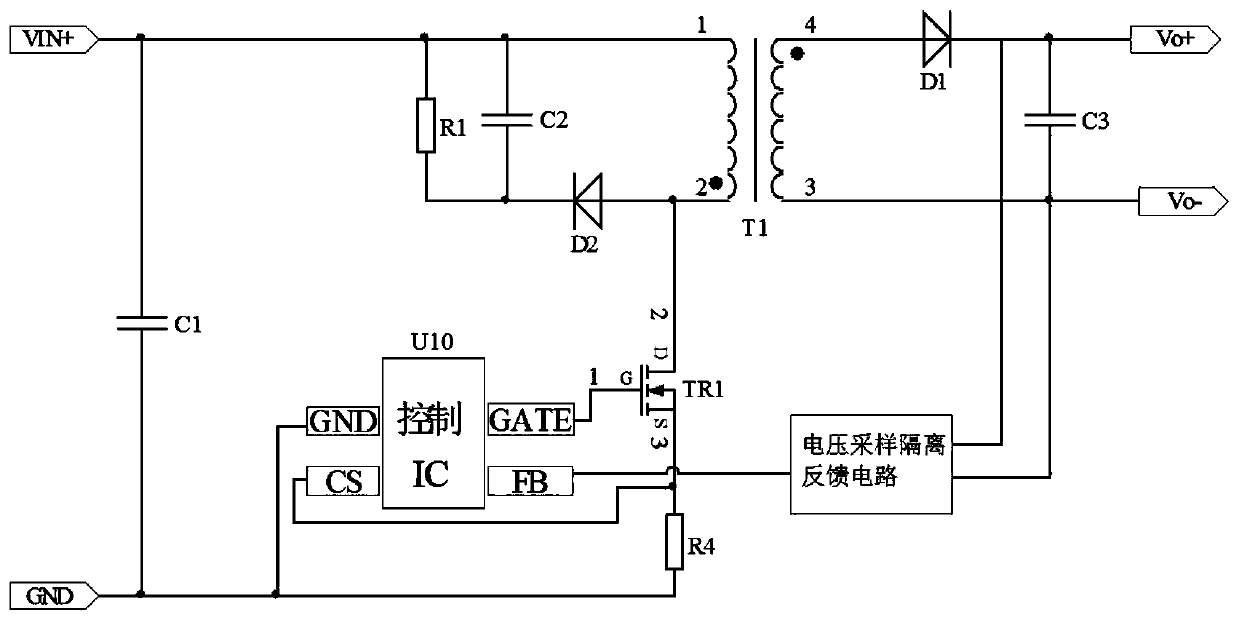
[0036] Figure 4 It is the circuit schematic diagram of the flyback converter of the present invention. The flyback converter includes a transformer T1, a primary side circuit, a secondary side circuit and a control circuit. The primary side circuit includes a filter capacitor C1, a main power circuit, a clamping circuit, and a current sampling circuit. And the voltage divider circuit, the main power circuit is formed by connecting the primary winding of the transformer T1 and the main switching tube TR1 (the main switching tube is a MOS tube, which may also be referred to as MOS tube TR1 below). The clamping module is formed by connecting a resistor R1, a capacitor C2 and a diode D2. The current sampling circuit is formed by connecting resistor R4. The secondary circuit is composed of the secondary winding of the transformer T1, the diode D1, and the capacitor C3. The control circuit consists of a control chip U1 and a voltage sampling isolation feedback circuit. The contro...
Embodiment 2
[0047] Figure 8 It is the circuit schematic diagram of the valley control circuit of the second embodiment of the present invention applied in the flyback converter. Compared with the first embodiment, the main MOS transistor TR1 of the flyback converter and the resistor R4 of the current sampling circuit are used in the second embodiment It is integrated into the chip of the control chip U1', which simplifies the peripheral parameters. The control chip U1' includes UVP pins, GND pins, DRIN pins and FB pins. The UVP pins are input voltage detection pins, which are used to detect the gears of the input voltage to determine which valleys to open and do Undervoltage protection; the GND pin is the reference ground pin of the chip; the DRIN pin is the drain pin of the switch tube, which is used to sample the waveform of the drain of the built-in MOS transistor TR1, and provide it to the valley control circuit to count the number of valleys ; and as the drain terminal of the built...
PUM
 Abstract
Description
Claims
Application Information
 - R&D
- Intellectual Property
- Life Sciences
- Materials
- Tech Scout
- Unparalleled Data Quality
- Higher Quality Content
- 60% Fewer Hallucinations
Browse by: Latest US Patents, China's latest patents, Technical Efficacy Thesaurus, Application Domain, Technology Topic, Popular Technical Reports.
© 2025 PatSnap. All rights reserved.Legal|Privacy policy|Modern Slavery Act Transparency Statement|Sitemap|About US| Contact US: help@patsnap.com


