Metal plate member fixation device installation method

a metal plate member and fixing device technology, applied in the direction of screws, threaded fasteners, fastening means, etc., can solve the problems of wasting time and labor, and the installation of the metal plate member fixing device is quite simple, and achieves the effects of avoiding damage to the structural strength or change of physical properties, high durability of the component parts, and simple installation of the metal plate member fixing devi

Inactive Publication Date: 2010-11-18
WANG KUO CHUNG
View PDF12 Cites 17 Cited by
  • Summary
  • Abstract
  • Description
  • Claims
  • Application Information

AI Technical Summary

Benefits of technology

[0010]Further, the spring member has one positioning end thereof fastened to the retaining portion at the shoulder of the lock screw so that the locking device and the spring member can be installed in the barrel conveniently and rapidly by an automatic installation machine.
[0011]Further, because the lock screw, the cap and the spring member are not put in the reflow oven during the reflow soldering process to bond the barrel to the metal plate member, the invention avoids damage to the structural strength or change of physical properties of the lock screw, cap and spring member of the metal plate member fixation

Problems solved by technology

Therefore, the installation of the metal plate member fix

Method used


Image

  • Metal plate member fixation device installation method
  • Metal plate member fixation device installation method
  • Metal plate member fixation device installation method

Examples


Embodiment Construction

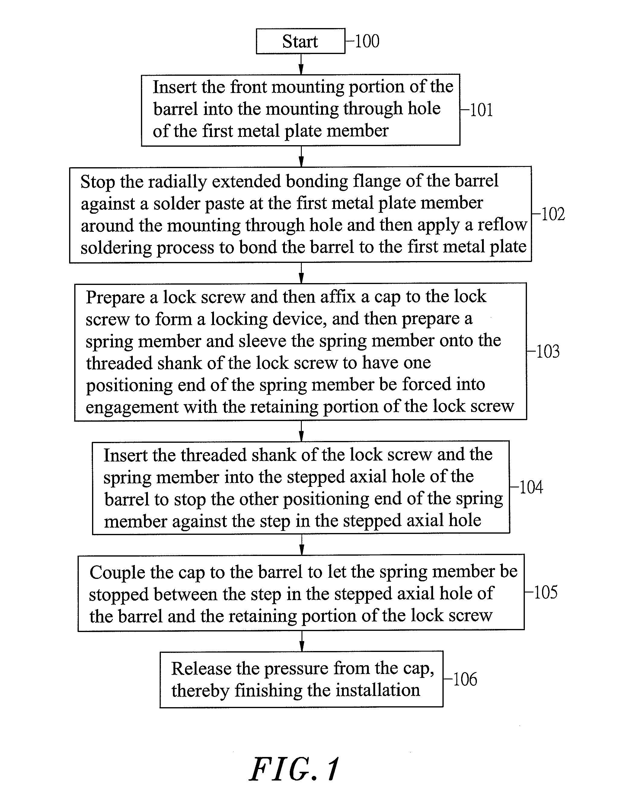
[0019]Referring to FIGS. 1˜4, a metal plate member fixation device installation method in accordance with the present invention includes the following steps:

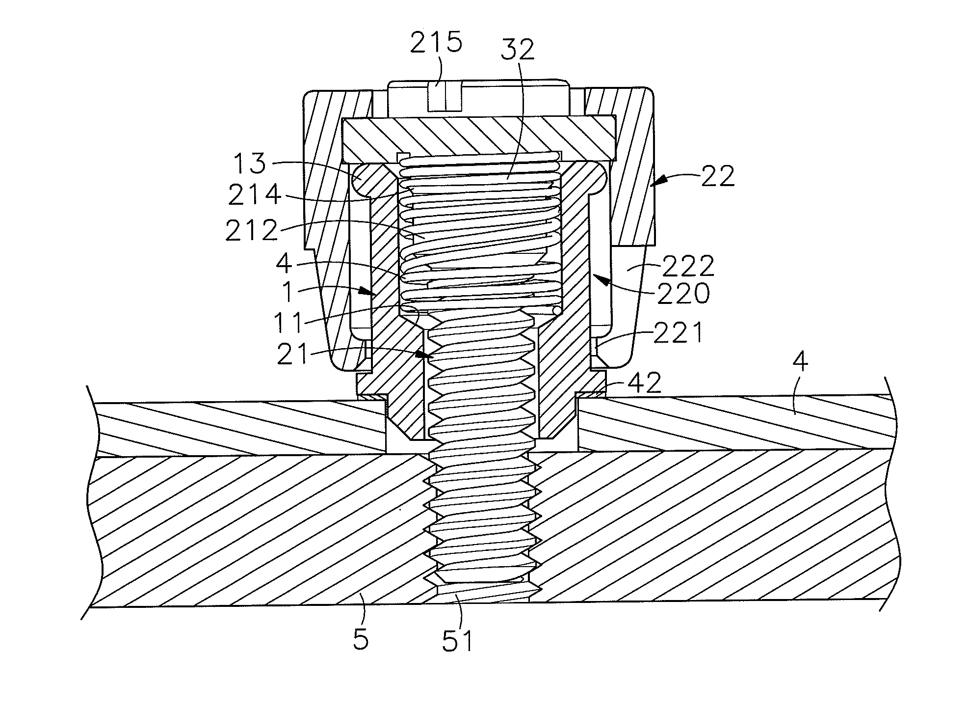
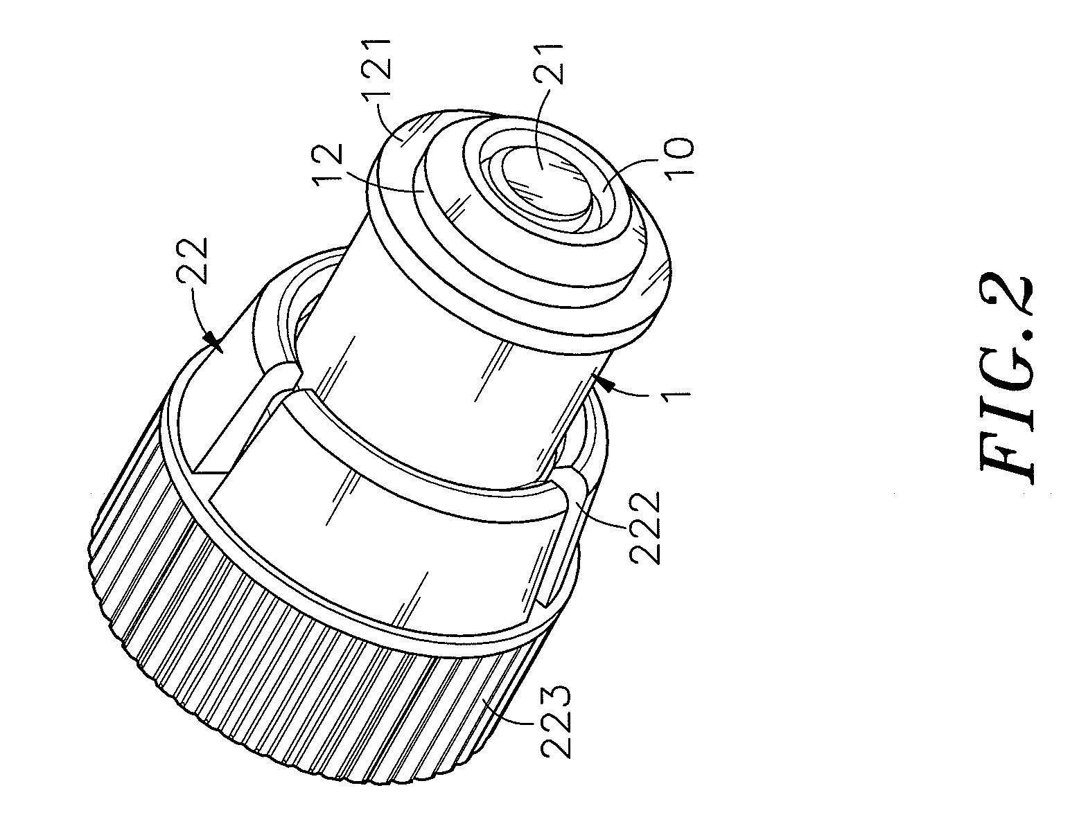
[0020](100) Prepare a barrel 1 that has a front mounting portion 12 with a radially extended bonding flange 121, a rear coupling flange 13 and a stepped axial hole 10 cut through the front and rear ends thereof;

[0021](101) Insert the front mounting portion 12 of the barrel 1 into a mounting through hole 41 of a first metal plate member 4;

[0022](102) Stop the radially extended bonding flange 121 of the front mounting portion 12 against a solder paste 42 on the top wall of the first metal plate member 4 around the mounting through hole 41, and then apply a reflow soldering process to bond the bottom bonding flange 121 of the barrel 1 to the first metal plate member 4 in a reflow oven;

[0023](103) Prepare a lock screw 21 that has a head 211, a threaded 213 perpendicularly extended from the center of the bottom wall of the head 211, ...


PUM


Abstract

A metal plate member fixation device installation method includes the step of preparing a barrel and inserting the front mounting portion of the barrel into a mounting through hole of a metal plate member and then bonding the barrel to the first metal plate member by a reflow soldering process, the step of providing a locking device formed of a lock screw and a cap and then sleeving a spring member onto the lock screw to force one end of the spring member into engagement with a retaining portion at the shoulder of the lock screw, the step of axially slidably coupling the cap of the locking device to the barrel to let the spring member be stopped between a step in the barrel and the retaining portion of the lock screw, and the step of releasing the pressure from the cap to finish the installation.

Description

[0001]This is a continuation-in-part application of Ser. No. 12 / 464,888, filed on May 13, 2009, entitled “Fastener”.BACKGROUND OF THE INVENTION[0002]1. Field of the Invention[0003]The present invention relates to the application of a metal plate member fixation device for joining two metal plate members and more particularly, to a metal plate member fixation device installation method, which facilitates installation of a metal plate member fixation device by an automatic installation machine, avoiding falling of component parts during installation, assuring high installation quality and saving much the installation cost.[0004]2. Description of the Related Art[0005]When fastening plate members together, a positioning screw formed of a knob, a ring and a screw nail is usually used. During installation, the screw nail and the ring are secured to the first plate member, and then the knob is rotated to drive the screw nail into the second plate member, and then a hand tool is used to fas...

Claims


Application Information

Patent Timeline
IPC IPC(8): F16B39/00
CPCF16B5/0208
Inventor WANG, KUO-CHUNG
Owner WANG KUO CHUNG
Why Eureka
Try Eureka