
Air flare apparatus and method

Inactive Publication Date: 2010-11-18
JOHN ZINK CO LLC
View PDF103 Cites 31 Cited by
  • Summary
  • Abstract
  • Description
  • Claims
  • Application Information

AI Technical Summary

Benefits of technology

[0015]The objects, features and advantages of the present invention will be readily apparent to those skilled in the art upon a reading of the following detailed description.

Problems solved by technology

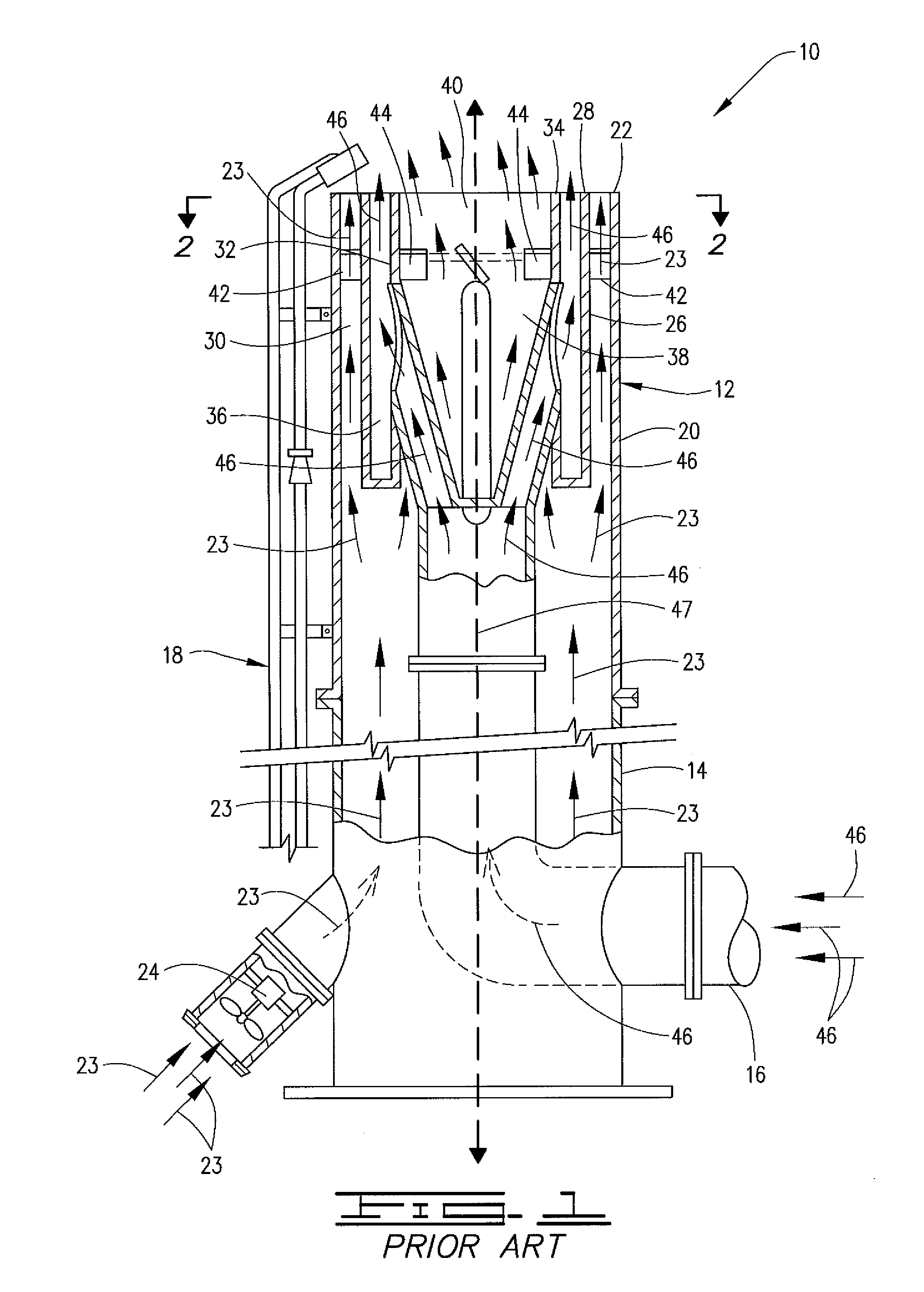
Internal burning, that is the burning of portions of the flare gas and air within the flare tip and other structure, can cause the flare apparatus to have a relatively short service life.
Repairing and / or replacing the flare apparatus or parts thereof is expensive and can result in costly interruptions of the corresponding facility or plant.
Unfortunately, such a mixing system may not be as efficient as possible in all applications.
However, in certain applications, this approach can lead to internal burning and significantly shorten the service life of the flare tip.

Method used


Image

  • Air flare apparatus and method
  • Air flare apparatus and method
  • Air flare apparatus and method

Examples


example

[0098]The inventive flare apparatus 50 was operated to smokelessly fire about 84,000 lb / hr of propane with about 34,000 standard cubic feet per minute of air representing about 13% of the theoretically required stoichiometric air requirement for complete combustion of propane. The flame outline shown by FIG. 14A was produced. Conventional air flare technology would have required about 30% of the theoretical stoichiometric rate or more than twice as much air. That is, the inventive technology required about half of the customary airflow to achieve smokeless operation.


PUM


Abstract

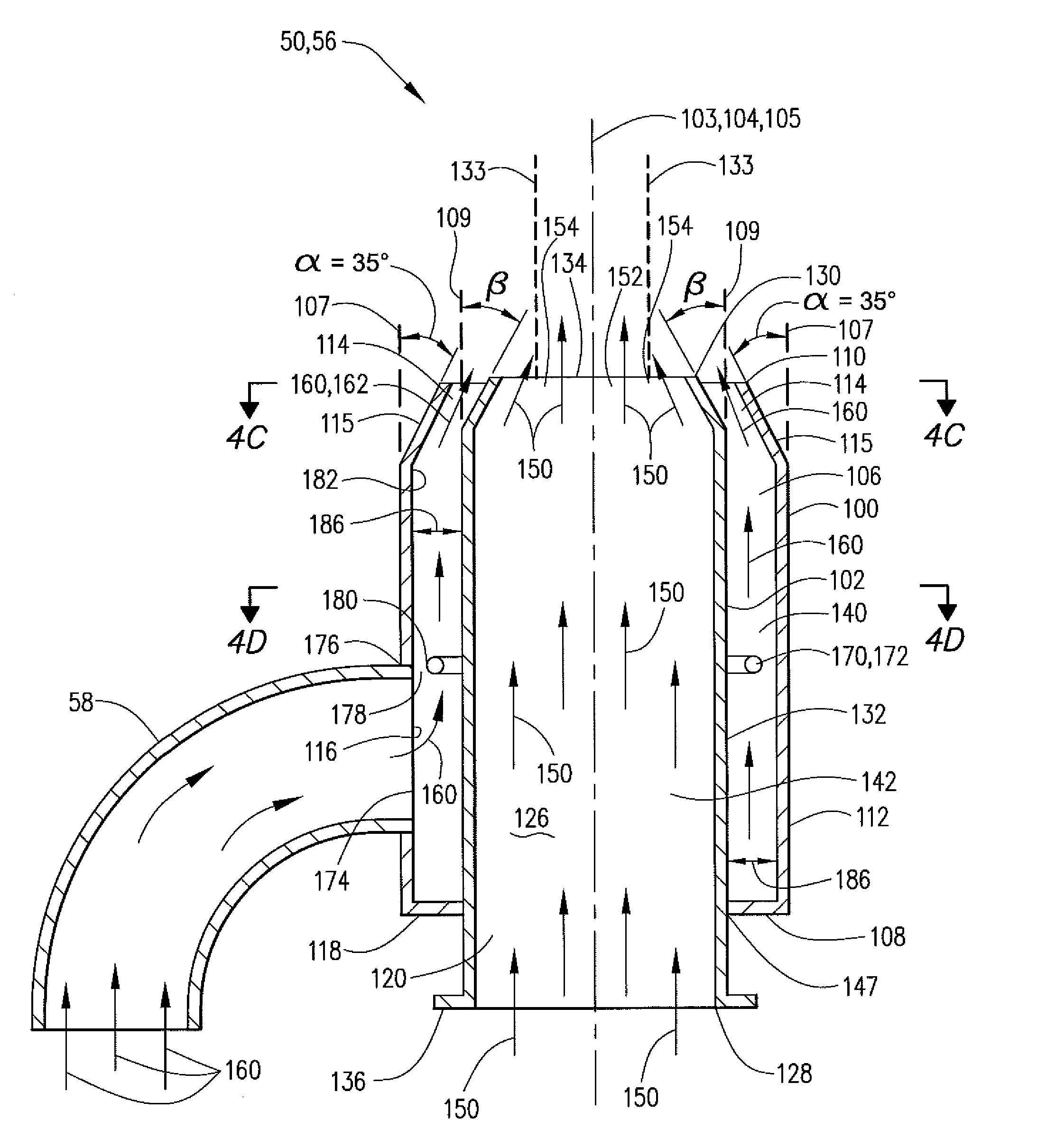
A flare apparatus for discharging and burning flare gas in the atmosphere is provided. The flare tip includes a flare gas conduit having a flare gas discharge opening and a combustion air conduit having a combustion air discharge opening. All of the flare gas to be flared is discharged through the flare gas discharge opening into a unified column of air discharged through the combustion air discharge opening. The flare gas discharge opening and the combustion air discharge opening are positioned with respect to one another such that flare gas discharged from the flare gas discharge opening is discharged inwardly into combustion air that is discharged from the combustion air discharge opening and admixed therewith. Essentially all of the discharged flare gas is admixed with discharged combustion air or external atmospheric air outside of the flare apparatus thereby preventing internal burning. A method of flaring a mixture of flare gas and combustion air is also provided.

Description

BACKGROUND OF THE INVENTION[0001]Gas flares are commonly located at production facilities, refineries, processing plants and the like for disposing of flammable waste gases and other flammable gas streams that are diverted due to venting requirements, shut-downs, upsets and / or emergencies. Such flares are often required to operate in a smokeless manner, which has been achieved by making sure that the flammable gas to be discharged and burned (“flare gas”) is admixed with enough air to sufficiently oxidize the gas. A typical flare apparatus includes a flare stack, which can extend high above the ground, and a flare tip mounted on the flare stack.[0002]In an air-assist flare, one or more blowers are used to blow air up through the flare stack. In a steam-assist flare, steam is used to provide the necessary motive force and entrainment energy to augment air from around the flare apparatus. Some flares utilize both forced air and steam to achieve the desired result.[0003]In addition to ...

Claims


Application Information

Patent Timeline
IPC IPC(8): F23G7/08F23D14/22
CPCF23G7/085F23G7/08
Inventor POE, ROGER L.COLANNINO, JOSEPHHONG, JIANHUISCHWARTZ, ROBERT E.
Owner JOHN ZINK CO LLC
Features
  • Generate Ideas
  • Intellectual Property
  • Life Sciences
  • Materials
  • Tech Scout
  • Unparalleled Data Quality
  • Higher Quality Content
  • 60% Fewer Hallucinations
Learn More