
Mode-Matching Apparatus and Method for Micromachined Inertial Sensors

a technology of inertial sensor and mode matching, which is applied in the direction of acceleration measurement using interia force, turn-sensitive devices, instruments, etc., can solve the problems of affecting the performance of gyroscopes, and affecting the coriolis signal

Active Publication Date: 2010-11-25
ANALOG DEVICES INC
View PDF37 Cites 47 Cited by
  • Summary
  • Abstract
  • Description
  • Claims
  • Application Information

AI Technical Summary

Benefits of technology

[0011]Embodiments of the present invention utilize a simple mode-frequency matching servo mechanism that utilizes a single-frequency test signal and does not af...

Problems solved by technology

One problem in the manufacture of MEMS gyroscopes is that the Coriolis signals on which they depend are relatively small.
Such phase shifts are particularly deleterious to gyroscope performance, so it is generally necessary, in practice, to either well separate the frequencies or tightly servo the frequency of the accelerometer to the frequency of the shuttle.
This inevitably interferes with the Coriolis signal and effectively is only applicable to those gyroscopes that do not need static response, such as camera stabilizing gyros.
Generally speaking, quadrature error results when the vibratory motion is not perfectly orthogonal to the accelerometer.
In-phase error results when the vibratory drive force is not perfectly orthogonal to the accelerometer.
One possible approach to reducing gyroscope offset is to attempt to minimize the offset through device design, manufacture, and packaging, but there are practical limits to this approach.

Method used


Image

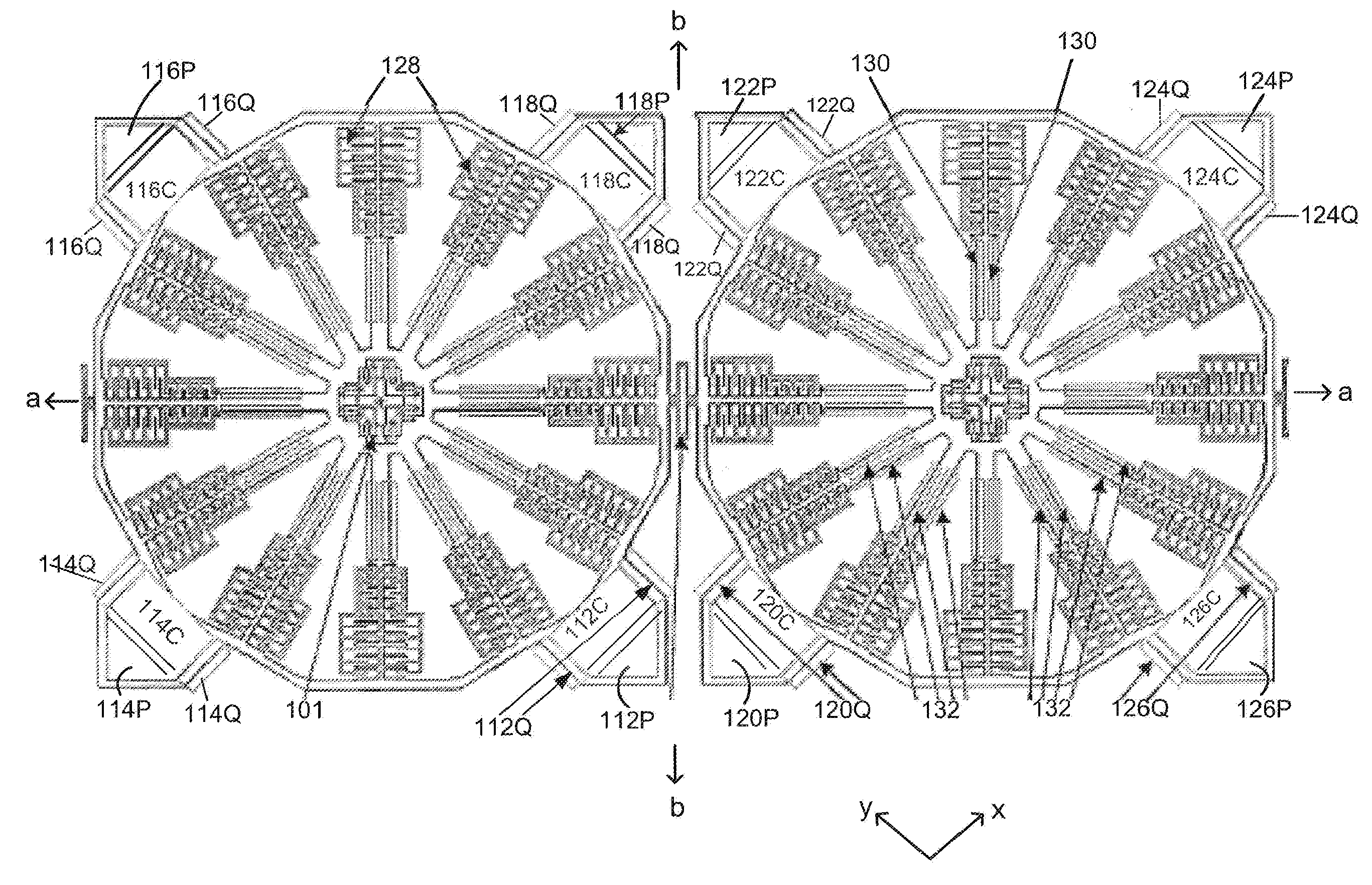
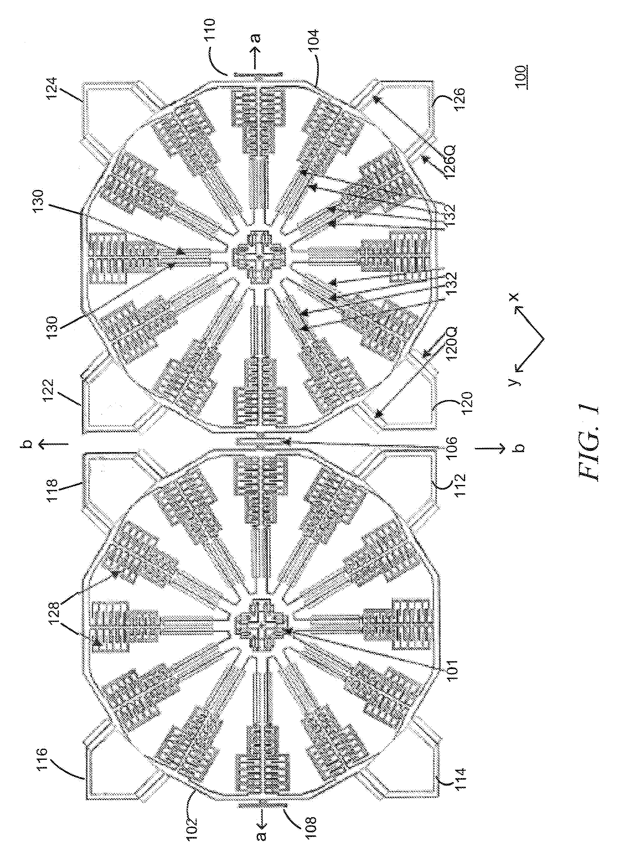
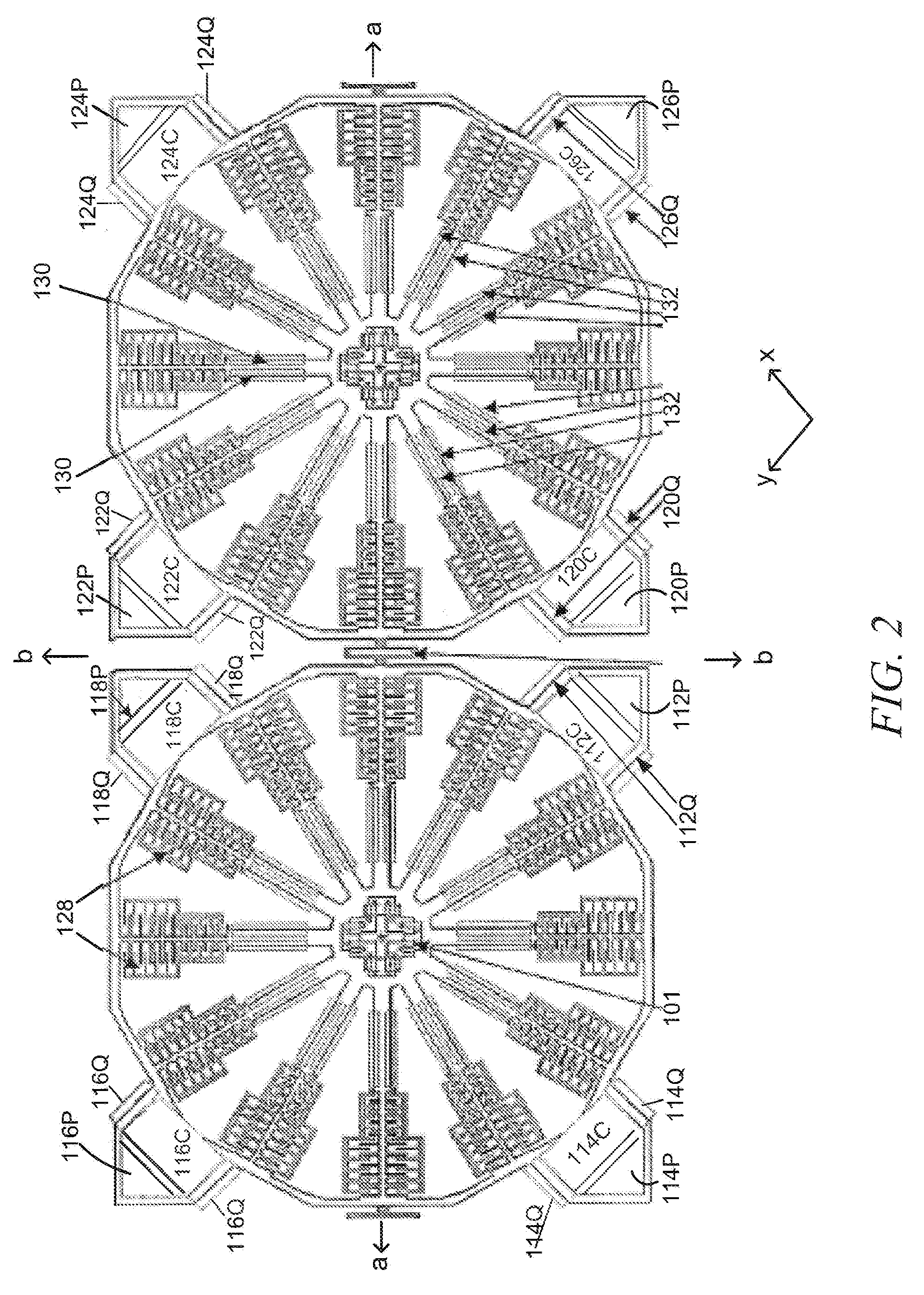
  • Mode-Matching Apparatus and Method for Micromachined Inertial Sensors
  • Mode-Matching Apparatus and Method for Micromachined Inertial Sensors
  • Mode-Matching Apparatus and Method for Micromachined Inertial Sensors

Examples


Embodiment Construction

[0032]Definitions. As used in this description and the accompanying claims, the following terms shall have the meanings indicated, unless the context otherwise requires.

[0033]A “set” includes one or more elements.

[0034]An “electrode” is a structure through which an electrical or electromechanical effect is applied and / or sensed. In exemplary embodiments, various electrodes are used for applying and / or sensing electrical or electromechanical effects through capacitive coupling, although it should be noted that other types of electrodes and couplings may be used (e.g., piezoelectric).

[0035]The term “quality factor” or “Q-factor” or simply “Q” denotes a dimensionless parameter that compares the time constant for decay of an oscillating physical system's amplitude to its oscillation period. Equivalently, it compares the frequency at which a system oscillates to the rate at which it dissipates its energy. A higher Q indicates a lower rate of energy dissipation relative to the oscillation...


PUM


Abstract

A mode matching servo for an inertial sensor having a resonator and an accelerometer provides a test signal at a frequency higher than a predetermined inertial sensor response frequency and lower than an accelerometer resonance mode frequency so as to induce acceleration signals from the accelerometer substantially at the test signal frequency when the modes are not matched. A feedback signal is provided in response to such induced signals to substantially nullify the signals.

Description

TECHNICAL FIELD[0001]The present invention relates to micromachined inertial sensors, and more particularly to mode matching in micromachined inertial sensors.BACKGROUND ART[0002]Micromachined (MEMS) gyroscopes have become established as useful commercial items. Generally speaking, a MEMS gyroscope incorporates two high-performing MEMS devices, specifically a self-tuned resonator in the drive axis and a micro-acceleration sensor in the sensing axis. Gyroscope performance is very sensitive to such things as manufacturing variations, errors in packaging, driving, linear acceleration, and temperature, among other things. Basic principles of operation of angular-rate sensing gyroscopes are well understood and described in the prior art (e.g., Geen, J. et al., New iMEMS Angular-Rate-Sensing Gyroscope, Analog Devices, Inc., Analog Dialog 37-03 (2003), available at http: / / www.analog.com / library / analogDialogue / archives / 37-03 / gyro.html, which is hereby incorporated herein by reference in its...

Claims


Application Information

Patent Timeline
IPC IPC(8): G01C19/56
CPCG01C19/5776G01C19/5719G01C19/56
Inventor GEEN, JOHN A.
Owner ANALOG DEVICES INC
Learn More