Self-inserting seal assembly

a sealing assembly and self-inserting technology, applied in the direction of drilling casings, drilling pipes, well accessories, etc., can solve the problems of insufficient force applied by an rov, insufficient weight of the plug, and insufficient force applied by the rov to set the seal assembly for the plug rated for test pressure of 15,000 psi, etc., to achieve the effect of high pressure seals

Active Publication Date: 2010-11-25
VETCO GRAY
View PDF9 Cites 12 Cited by
  • Summary
  • Abstract
  • Description
  • Claims
  • Application Information

AI Technical Summary

Benefits of technology

[0007]In an embodiment of the present technique, a self-inserting seal assembly is provided that can allow high pressure seals in plugs to be set in well and riser components. The well and riser components can then be pressure tested to detect leaks after installation. The self-inserting seal assembly can be ROV installable and retrievable.

Problems solved by technology

However, plug seals used to conduct high pressure tests of well components can require setting forces of approximately 2,000 psi, depending on size.
The weight of the plug is thus insufficient to set these high pressure seals that can be rated for test pressures of up to 15,000 psi.
However, the force applied by an ROV may also be insufficient to set a seal assembly for a plug rated for test pressures of 15,000 psi or more.

Method used


Image

  • Self-inserting seal assembly
  • Self-inserting seal assembly
  • Self-inserting seal assembly

Examples


Embodiment Construction

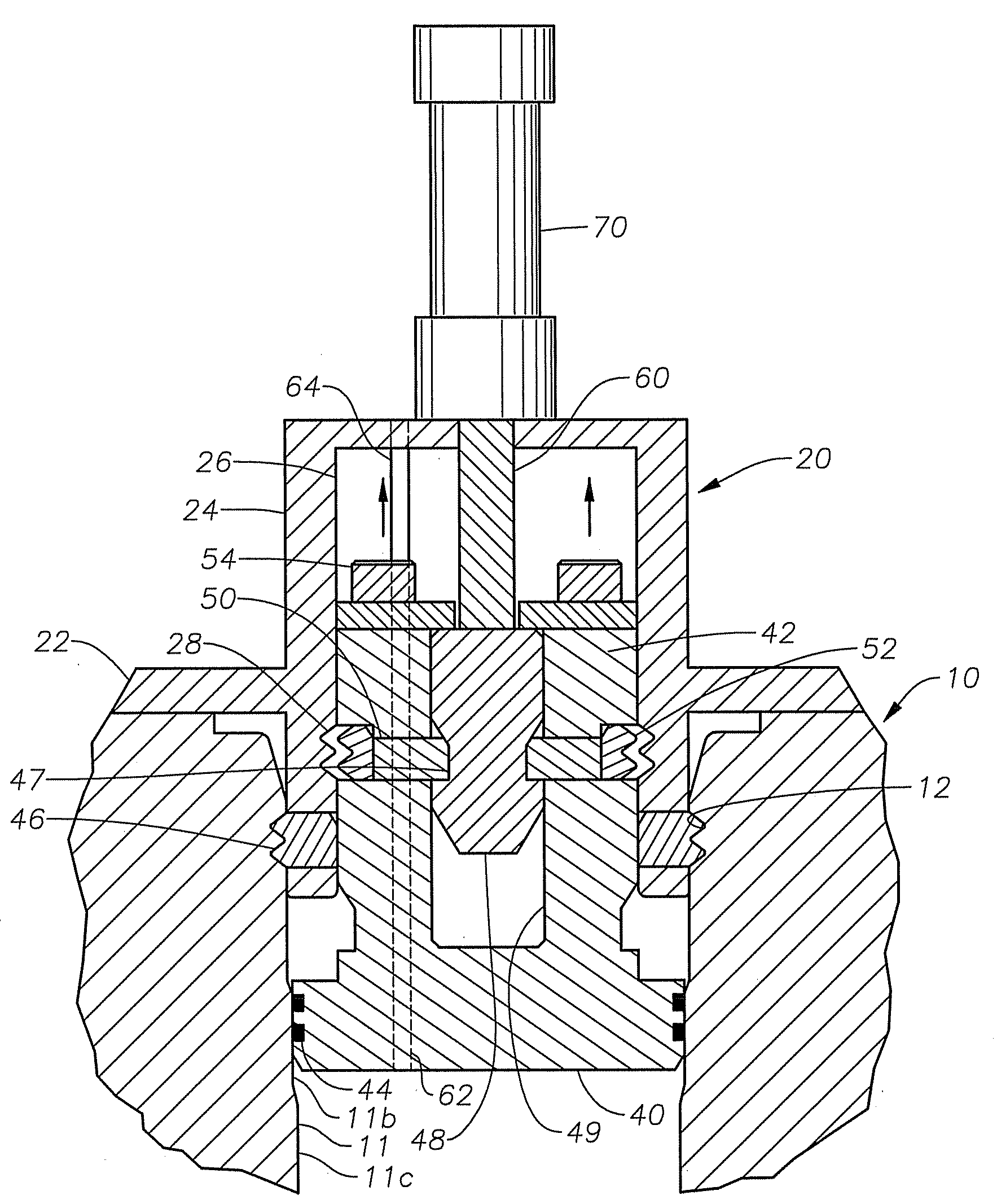
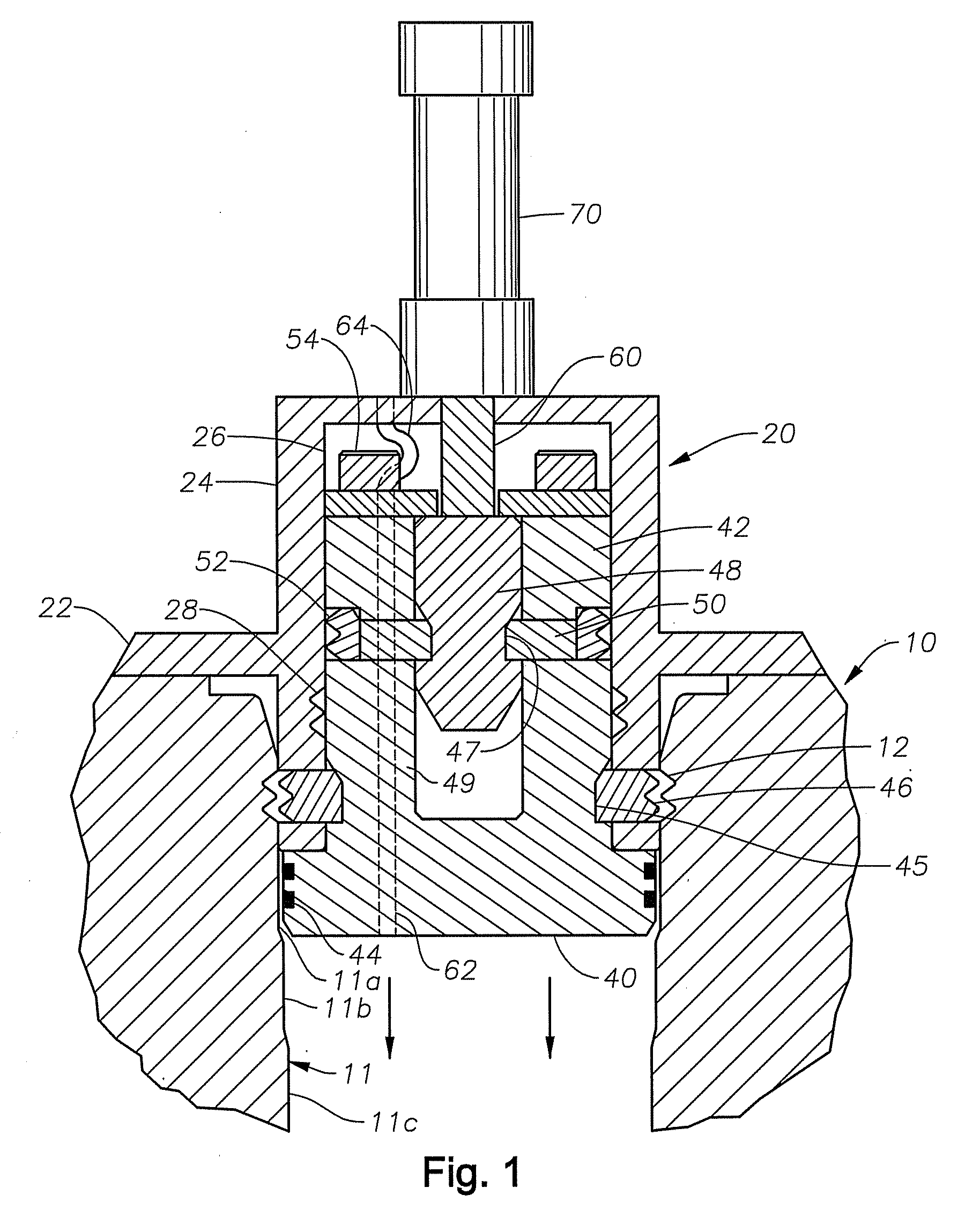
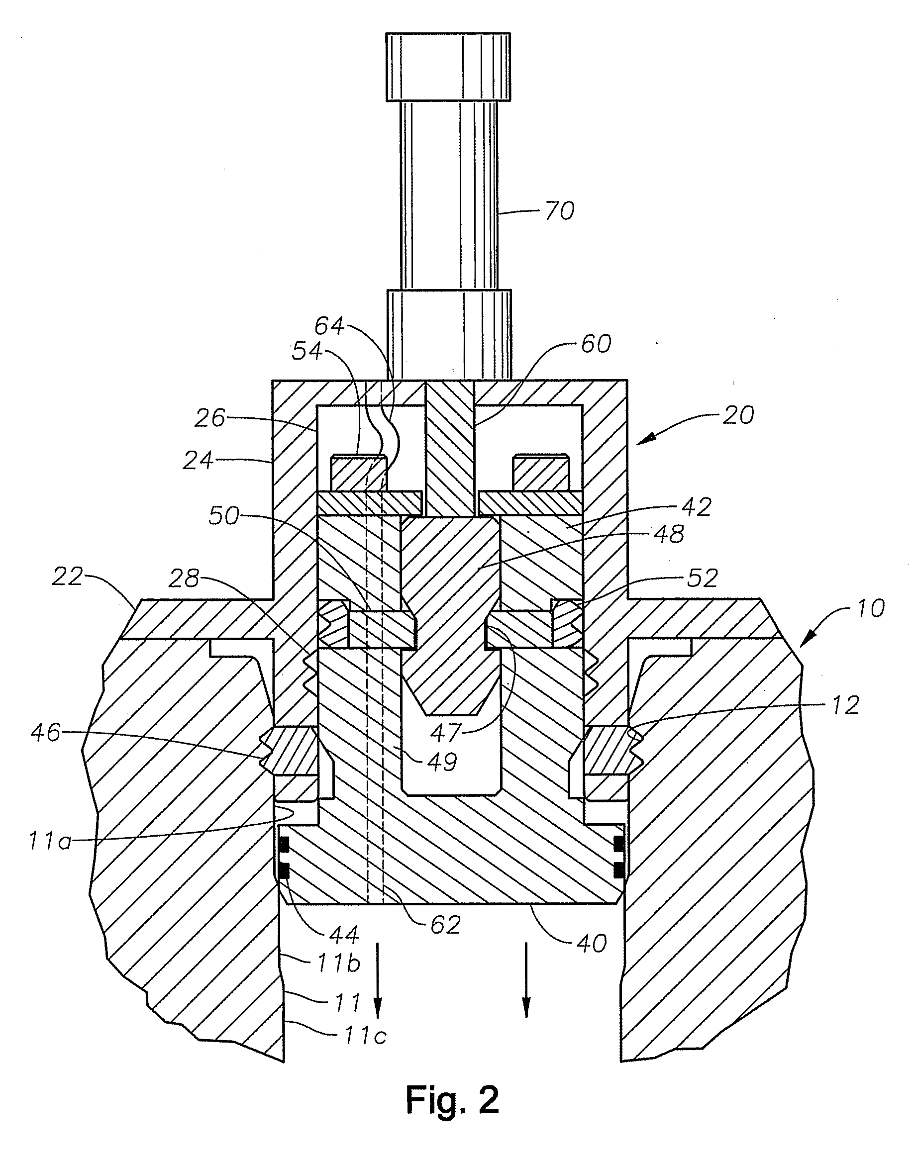
[0016]Referring to FIG. 1, an embodiment of the invention shows a portion of a well component 10, such as, for example a wellhead housing. Well component 10 is located at an upper end of a well and serves as a wellhead member in this example. Alternately, well component 10 could be a riser component instead of a wellhead member. The well component 10 has an inner diameter located therein.

[0017]In this example, the well component 10 comprises a bore 11 having a mating profile 12 formed on the inner diameter. The mating profile 12 can be comprised of annular grooves that interrupt the profile of the inner diameter. Bore 11 has an upper portion 11a and an annular seal surface 11b directly below. Seal surface 11b is smaller in diameter than bore upper portion 11a. A lower portion 11c is directly below seal surface 11b and can have a smaller inner diameter than the inner diameter of the seal surface 11b. However, it is not a requirement that the inner diameter of the lower portion 11c be...


PUM


Abstract

A self-inserting seal assembly that sets a seal at a well component to allow for pressure testing of the well component. The seal assembly can be landed on a well component with an ROV. A seal is located on the lower portion of a lower body in the assembly. A set of outer dogs lock with a grooved mating profile formed on the well component to lock the outer housing to provide a reaction point for setting the seal, which may require several thousand pounds of force. A set of inner dogs lock with a grooved mating profile formed on the inner diameter of the outer housing. This locks the lower body to the outer housing to ensure the seal remains set in place. After the well component is pressure tested, the seal assembly can be unlocked and retrieved from the well via an ROV.

Description

FIELD OF INVENTION[0001]This invention relates in general to seal assemblies and in particular to a seal assembly for a plug that can be used to seal and test a well component.BACKGROUND OF THE INVENTION[0002]A typical subsea wellhead assembly has a high pressure wellhead housing supported in a lower pressure wellhead housing and secured to casing that extends into the well. One or more casing hangers land in the wellhead housing, the casing hanger being located at the upper end of a string of casing that extends into the well to a deeper depth. A string of tubing extends through the casing for production fluids.[0003]Well components are pressure tested after installation to detect leaks. A plug comprising a seal can be used to pressure test the well components. The plug can be landed at a tubular well component and the seal can be set to establish a seal at the well component. The portion of the well below the plug can then be hydraulically pressurized from a remotely operated vehi...

Claims


Application Information

Patent Timeline
Patent Type & Authority Applications(United States)
IPC IPC(8): E21B23/00E21B49/10
CPCE21B41/04
Inventor PALLINI, JOSEPH W.LYLE, ROCKFORD D.LIN, CHII-REN
Owner VETCO GRAY
Why Eureka
Try Eureka