Detection of leakage in an air system of a motor vehicle

a technology of air system and motor vehicle, which is applied in the direction of electrical control, exhaust treatment electric control, instruments, etc., can solve the problems of limited regeneration of particulate filter, interrupted or broken off, and achieve the effect of increasing the service life of the exhaust gas system

Inactive Publication Date: 2013-04-23
ROBERT BOSCH GMBH
View PDF7 Cites 7 Cited by
  • Summary
  • Abstract
  • Description
  • Claims
  • Application Information

AI Technical Summary

Benefits of technology

[0005]It is an object of the exemplary embodiments and / or exemplary methods of the present invention to increase the service life of the exhaust gas system.
[0007]The exemplary embodiments and / or exemplary methods of the present invention have the advantage that leakage in the air supply channel is able to be detected. Consequently, appropriate measures may be taken in order to prevent an undesirably high temperature in the Diesel particulate filter in the regeneration operation, which is of advantage to the service life of the Diesel particulate filter. It is understood, in this context, however, that leakage in the air supply channel may have quite different causes: a wall of the air supply channel may have a hole in it, for example, a connection may have become loose or there may be a leakage place in the region of the throttle valve (throttle valve does not quite close). The measure according to the exemplary embodiments and / or exemplary methods of the present invention may be implemented without additional built-in components, in this context, so that hardly any additional costs are created.

Problems solved by technology

It is understood, in this context, however, that leakage in the air supply channel may have quite different causes: a wall of the air supply channel may have a hole in it, for example, a connection may have become loose or there may be a leakage place in the region of the throttle valve (throttle valve does not quite close).
For instance, the regeneration of the particulate filter may be limited, interrupted or broken off, or a late post-injection may be released into the oxidation catalyst of the exhaust gas aftertreatment system during an overrun phase of the internal combustion engine.

Method used


Image

  • Detection of leakage in an air system of a motor vehicle
  • Detection of leakage in an air system of a motor vehicle
  • Detection of leakage in an air system of a motor vehicle

Examples


Embodiment Construction

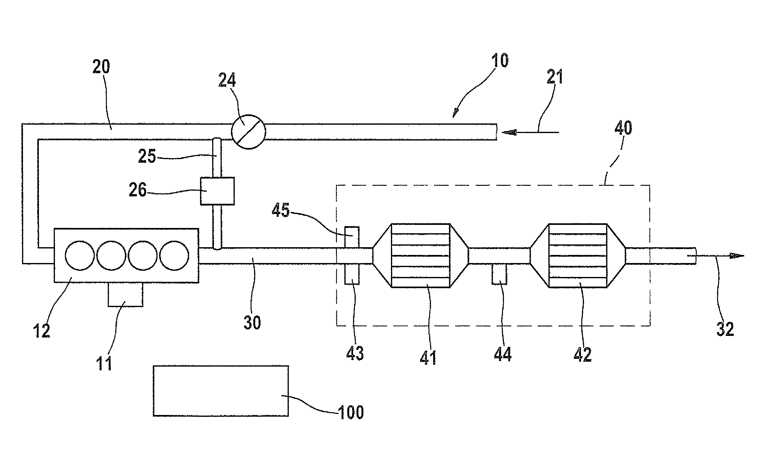
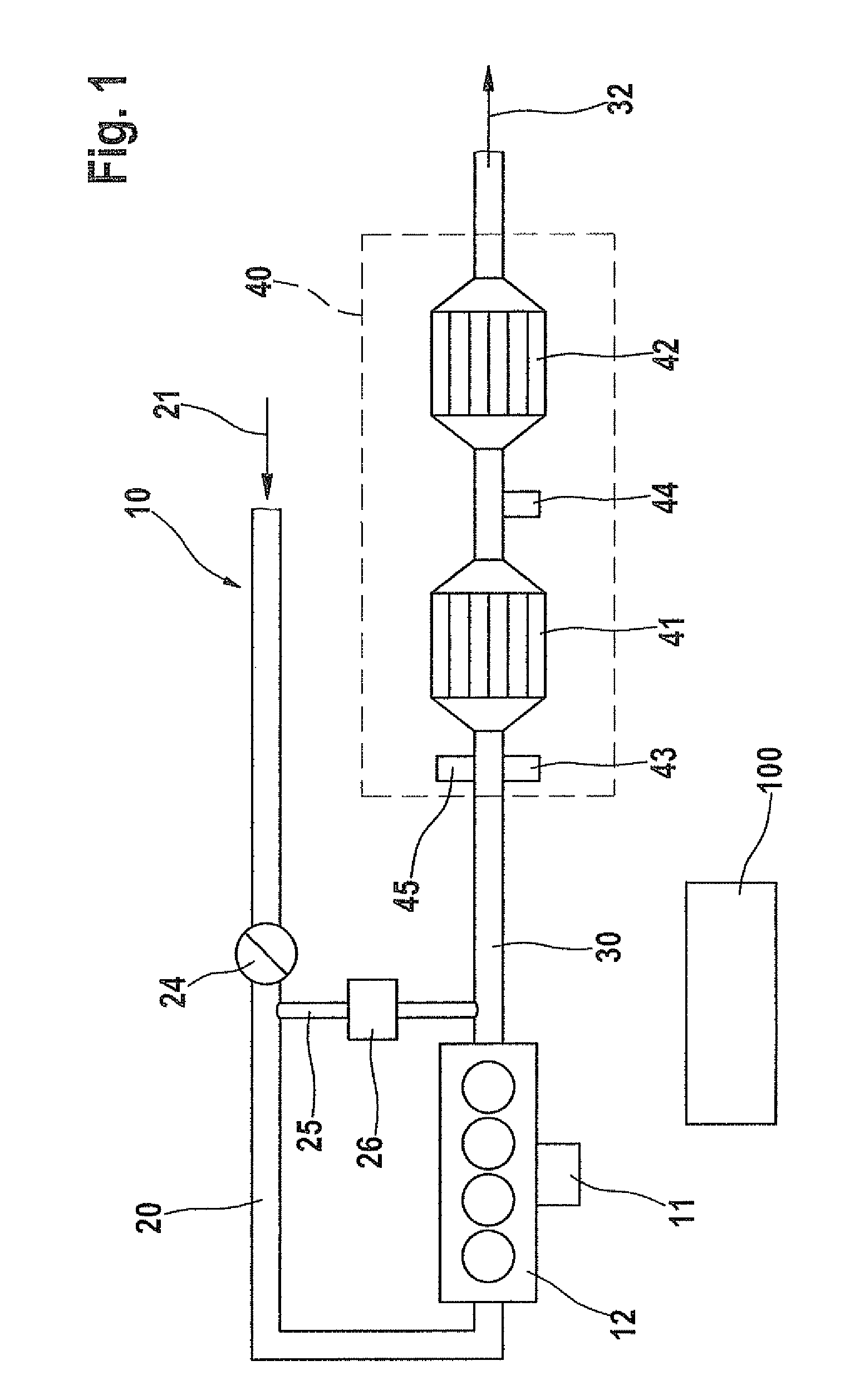
[0022]FIG. 1 shows a schematic representation of an internal combustion engine 10 in the form of a Diesel engine having a cylinder block 12, a fuel metering system 11, an air supply channel 20, in which an air supply flow 21 is guided, and an exhaust gas channel 30 in which an exhaust gas flow 32 of internal combustion engine 10 is guided. In air supply channel 20 there is a throttle valve 24. An exhaust gas recirculation 25 connects air supply channel 20, at least intermittently, to exhaust gas channel 30 via an exhaust gas recirculation valve 26. After cylinder block 12, in the flow direction of exhaust gas flow 32, as components of an exhaust gas aftertreatment system 40 that is associated with internal combustion engine 10, the following are shown: a first lambda probe 43, a fuel supply 45 (optional), an oxidation catalytic converter 41 in the form of a Diesel oxidation catalytic converter, a second lambda probe 44 and a Diesel particulate filter 42. The exhaust gas system of a ...


PUM


Abstract

A method is described for operating an internal combustion engine in motor vehicles, in which air is supplied to a combustion chamber via a throttle valve and an air supply channel, and in which exhaust gas is conducted through a particulate filter and is returned at least intermittently and at least partially through an exhaust gas recirculation valve into the air supply channel, and in which an oxygen proportion in the exhaust gas is detected using at least one lambda probe. In this context, in an overrun operation, the throttle valve is controlled to close and the exhaust gas recirculation valve is controlled to open, a variable characterizing the oxygen concentration in the exhaust gas is compared to a boundary value, and as a function of the result of the comparison, it is concluded that there is a leakage in the air supply channel.

Description

RELATED APPLICATION INFORMATION[0001]The present application claims priority to and the benefit of German patent application no. 10 2009 001 626.0, which was filed in Germany on Mar. 18, 2009, and German patent application no. 10 2009 027 519.3, which was filed in Germany on Jul. 8, 2009, the disclosures of which are incorporated herein by reference.FIELD OF THE INVENTION[0002]The present invention relates to a method, as well as a computer program, an electrical storage medium and a control and / or a regulating device for a system for exhaust gas aftertreatment in motor vehicles.BACKGROUND INFORMATION[0003]An internal combustion engine is understood to be known in the market, that is equipped with a particulate filter, and in which the soot burn-off is controlled or checked, in order to protect the particulate filter. Such a system, with the corresponding method, is discussed in DE 10 2007 010 189 A1, in order to regulate the temperature of the exhaust gas during a regeneration proc...

Claims


Application Information

Patent Timeline
Patent Type & Authority Patents(United States)
IPC IPC(8): F02M25/06
CPCF01N3/103F01N13/009F01N11/007F02D11/107F02D41/0077F02D41/221F02M25/0702F01N2430/085F01N2560/025F02D41/0002F02D41/1454F02D2041/0017F02D2041/0022Y02T10/47F01N9/002F02M26/49Y02A50/20Y02T10/40
Inventor DE TRICAUD, STEPHANEJAEGER, DANNY
Owner ROBERT BOSCH GMBH
Why Eureka
Try Eureka