
Reusable fitting, connector assembly and kit

Inactive Publication Date: 2008-11-06
HOWARD JOSEPH D +1
View PDF7 Cites 29 Cited by
  • Summary
  • Abstract
  • Description
  • Claims
  • Application Information

AI Technical Summary

Benefits of technology

[0019]It is a further aspect of the invention to provide an improved three-piece reusable tri-clamp style connector assembly that allows a user to accurately determine when the nut is sufficiently tightened onto the fitting.
[0020]It is a further aspect of the invention to provide an improved three-piece reusable tri-clamp style connector assembly that doesn't require factory installation in order to achieve a high-pressure seal

Problems solved by technology

One problem with the use of flexible tubing is the need to connect the tubing to the source of gaseous or liquid fluid, the delivery site of the fluid, or to another flexible tubing.
Given the relatively high cost of such fittings, there was a need for a reusable sanitary fitting for use with such hoses and tubing.
Although the three-piece reusable tri-clamp style connector assembly described above is effective at joining lengths of flexible hose, it is not without its drawbacks.
First, these three-piece reusable tri-clamp style fittings do not include any easy means for holding the fitting in a stationary position while the nut is being tightened.
Such tools can lead to a marring of the surface of the fitting, which is unacceptable in sanitary applications and may cause the fitting to need to be replaced.
These tools are often cumbersome to use on a jobsite and the failure to have such a tool results in the fitting not being able to be effectively secured.
Another drawback inherent in conventional three-piece reusable tri-clamp style connector assemblies is the inability of the assembler to determine when the nut is sufficiently tightened onto the fitting.
Accordingly, there is often great variation in how much the nuts are tightened, with some being insufficiently tightened and others over tightened to the point where the crimp sleeve causes damage to the hose.
Thus, it is not uncommon for users of these fittings to require that the manufacturer attach the assembly to the hose or tubing, significantly increasing the time and cost involved.
Further, in cases where the users do attach the assembly themselves, such uses are typically in lower pressure applications where the risk of under-tightening is low.

Method used


Image

  • Reusable fitting, connector assembly and kit
  • Reusable fitting, connector assembly and kit
  • Reusable fitting, connector assembly and kit

Examples


Embodiment Construction

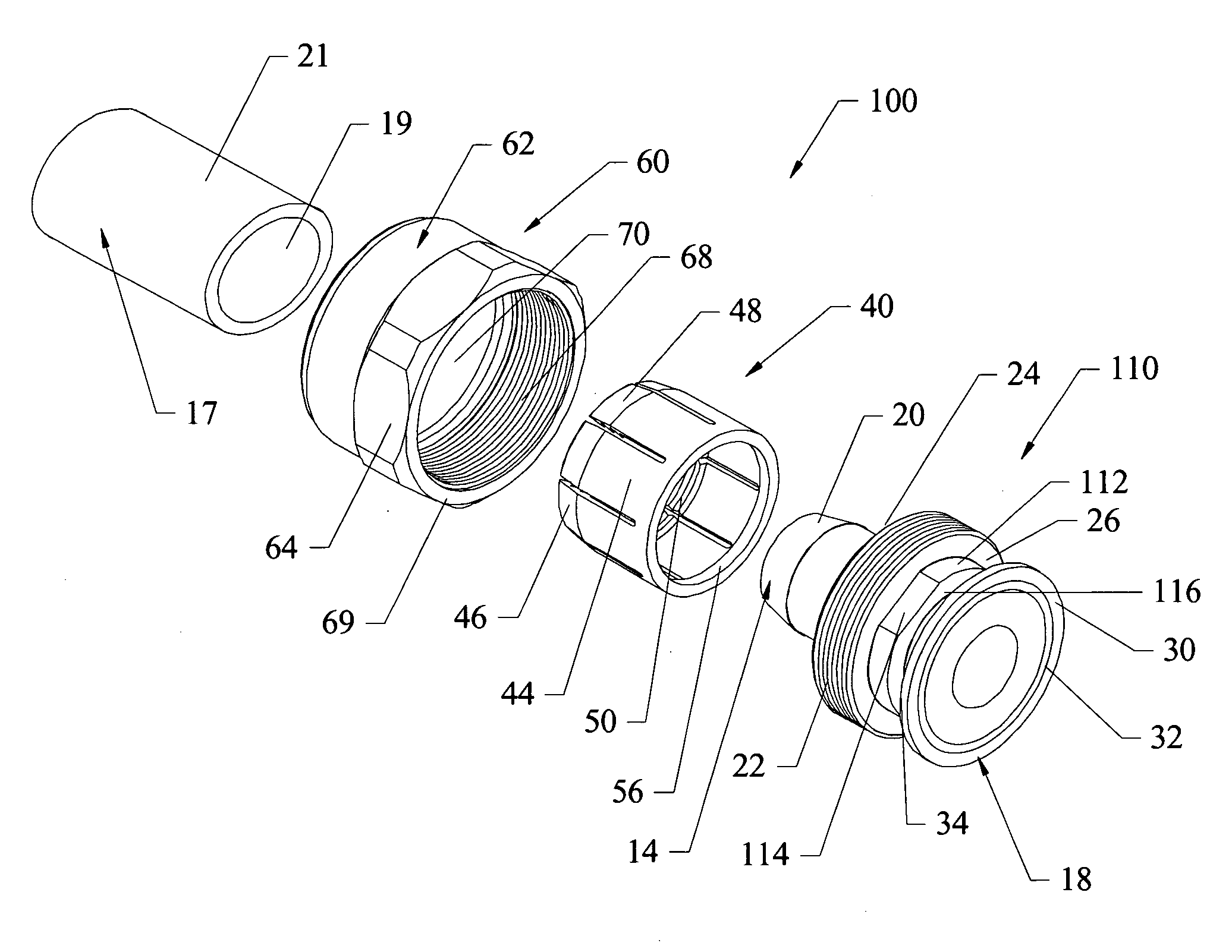
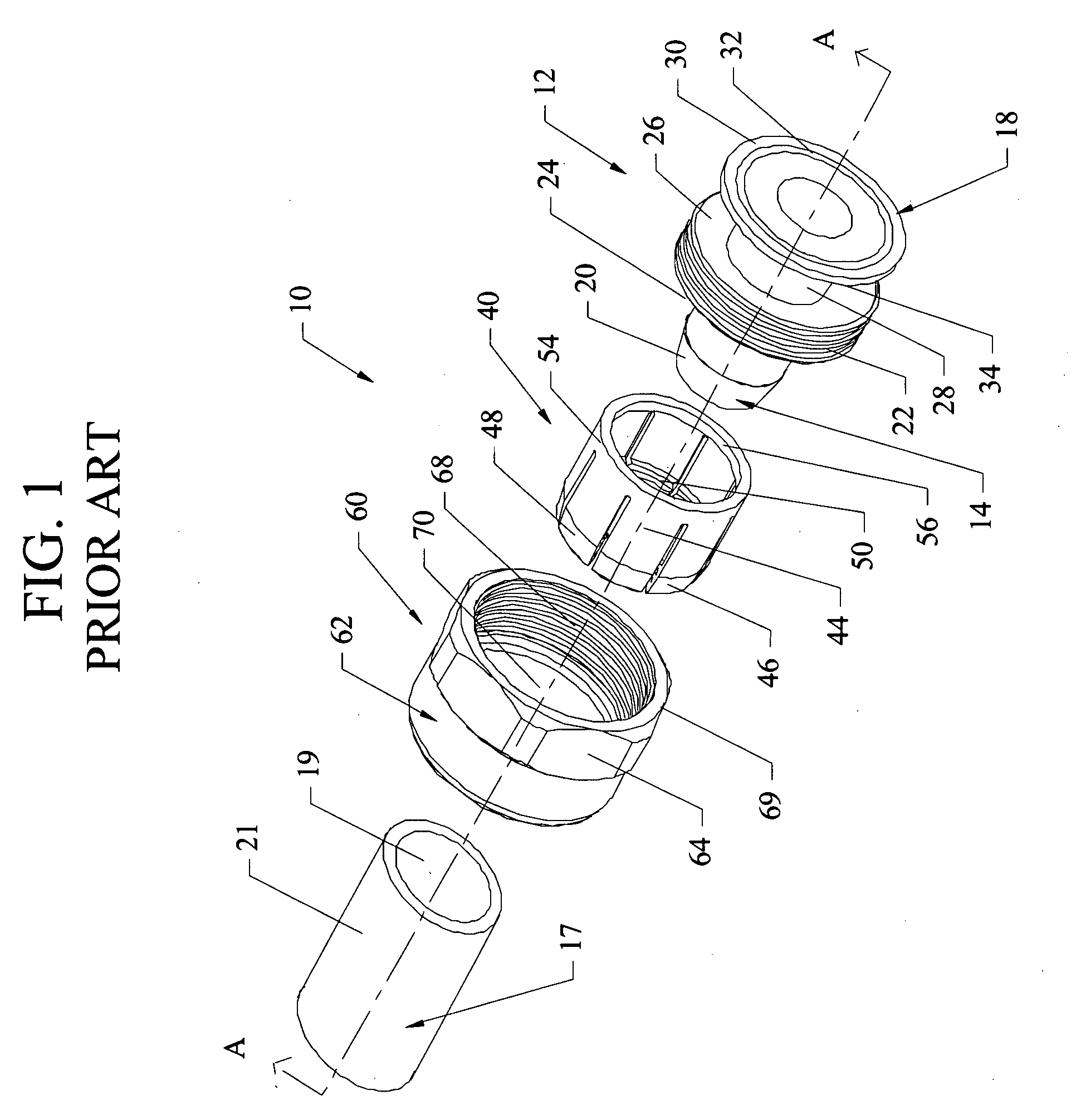
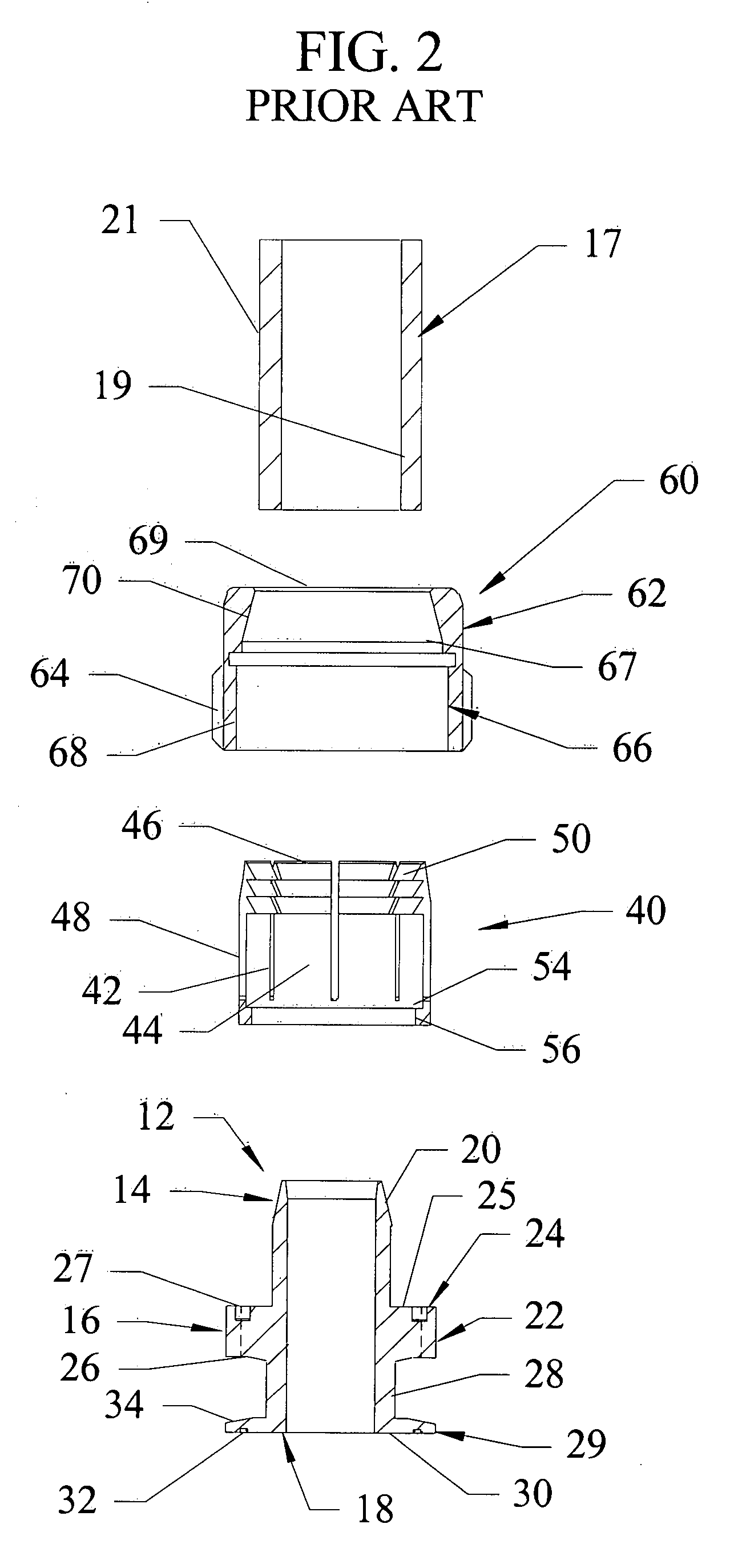
[0039]FIGS. 1-3 shows a conventional three-piece reusable sanitary tri-clamp style connector assembly 10. This connector assembly 10 includes a fitting 12, a crimp sleeve 40, and a nut 60, which are assembled together to form a removable termination for a hose 17 or tube.

[0040]Looking first to the fitting 12, the fitting 12 has a barb portion 14, a threaded portion 16, and a connector portion 18. The barb portion 14 is dimensioned to be inserted within the hose 17 and includes a securing barb 20 that grips the inside surface 19 of the hose 17 when the assembly 10 is assembled and prevents extraction of the hose 17 from the fitting 12. The threaded portion 16 has a larger diameter than the barb portion 14 and includes a threaded radial surface 22, a top surface 24, and a bottom surface 26. The top surface 24 includes a flat portion 25 having a width substantially equal to the thickness of the hose 17 and a radial groove 27 dimensioned to accept the crimp sleeve 40. The connector port...


PUM

PropertyMeasurementUnit
Fractionaaaaaaaaaa
Diameteraaaaaaaaaa

Abstract

A reusable fitting, connector assembly and kit. The reusable fitting includes a barb portion, a threaded portion, a tightening portion, a connector portion and a substantially smooth cylindrical bore extending through the barb portion, threaded portion, tightening portion and connector portion. The tightening portion is disposed proximate to the threaded portion and includes least two parallel tightening surfaces. The connector assembly includes the fitting, a nut and a crimp sleeve. The kit includes the connector assembly and at least one wrench.

Description

FIELD OF THE INVENTION[0001]The present invention relates to the field of fittings for connecting sections of flexible hose and, in particular, to reusable sanitary fittings for connecting sections of flexible hose used in sanitary applications.BACKGROUND OF THE INVENTION[0002]Product contamination is a major concern of producers of a large number of products, including producers of food products, medical products, pharmaceuticals, biotechnology products, electronics, and personal care products. For this reason, the equipment used to manufacture these products must be designed to limit points where such contamination is likely to occur and, once it is put into use, the equipment must be frequently cleaned and sanitized.[0003]The transfer of fluid through flexible hose or tubing is widely used in a number of different processes. Flexible hose is preferred over stainless steel in many applications due to its lower cost, ease of installation, and the ability to easily modify the piping...

Claims


Application Information

Patent Timeline
IPC IPC(8): F16L33/00
CPCB25B13/08B25G1/105F16L33/224F16L19/06F16L19/00
Inventor HOWARD, JOSEPH D.MITCHELL, KEVIN J.
Owner HOWARD JOSEPH D
Learn More