Occupancy sensor and override unit for photosensor-based control of load

a technology of occupancy sensor and override unit, which is applied in the direction of optical radiation measurement, instruments, instruments for comonautical navigation, etc., can solve the problems of increasing labor, no way to add fixture override control to an existing installation, and the connector for fixture override, so as to reduce the light output of a lighting fixture load and off or reduce the energy consumption of the electrical load

Active Publication Date: 2010-11-25
HUBBELL LIGHTING INC
View PDF6 Cites 62 Cited by
  • Summary
  • Abstract
  • Description
  • Claims
  • Application Information

AI Technical Summary

Benefits of technology

[0013]One aspect of an illustrative embodiment of the present invention is to provide an occupancy sensor as a load controller having a photosensor for detecting daylight or ambient light which is able to turn off or lower the energy consumption of the electrical load or system when the light level within the target area is above a predetermined threshold level. A removable override system can be attached to the occupancy sensor to provide a light source directed toward the photosensor. The override system actuates the light source to project the light source to the light sensor, thereby signaling the occupancy sensor to operate the electrical system at lower power levels at predetermined times, for example.
[0014]One aspect of an illustrative embodiment of the present invention is to provide an occupancy sensor as a load controller having a recessed area with an open end facing away from the target area of the occupancy sen

Problems solved by technology

In previous products, there was no way to add fixture override control to an existing installation, if the original controller was not purchased with a class II control connector, without replacing the existing controller.
It is disadvantageous, however, to provide a connector for fixture override control on the housing of such an occupancy sensor for a number of reasons.
For example, such a connector would increase labor because Underwriter Laboratories, Inc. standards require a high potential test between

Method used


Image

  • Occupancy sensor and override unit for photosensor-based control of load
  • Occupancy sensor and override unit for photosensor-based control of load
  • Occupancy sensor and override unit for photosensor-based control of load

Examples


Embodiment Construction

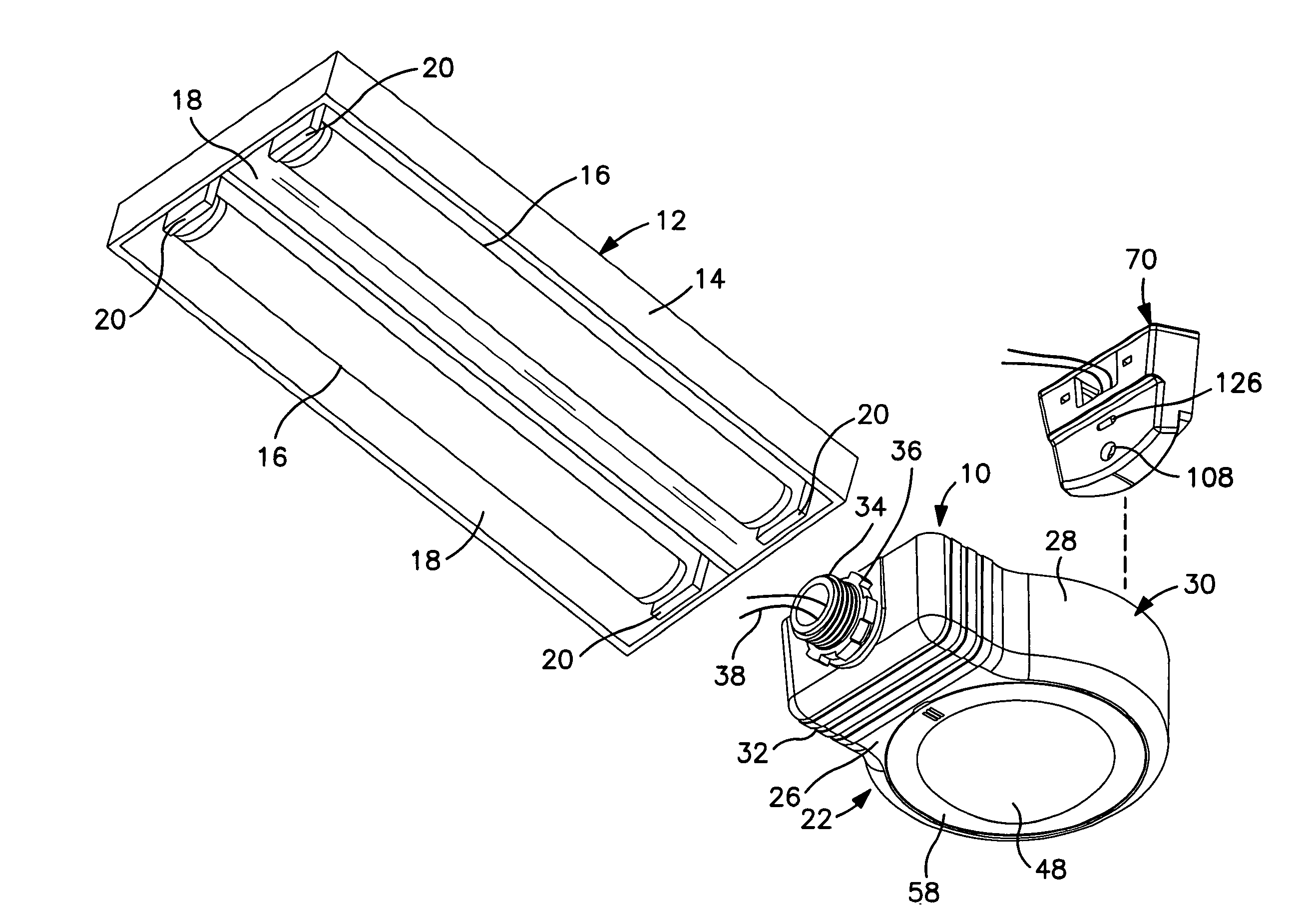
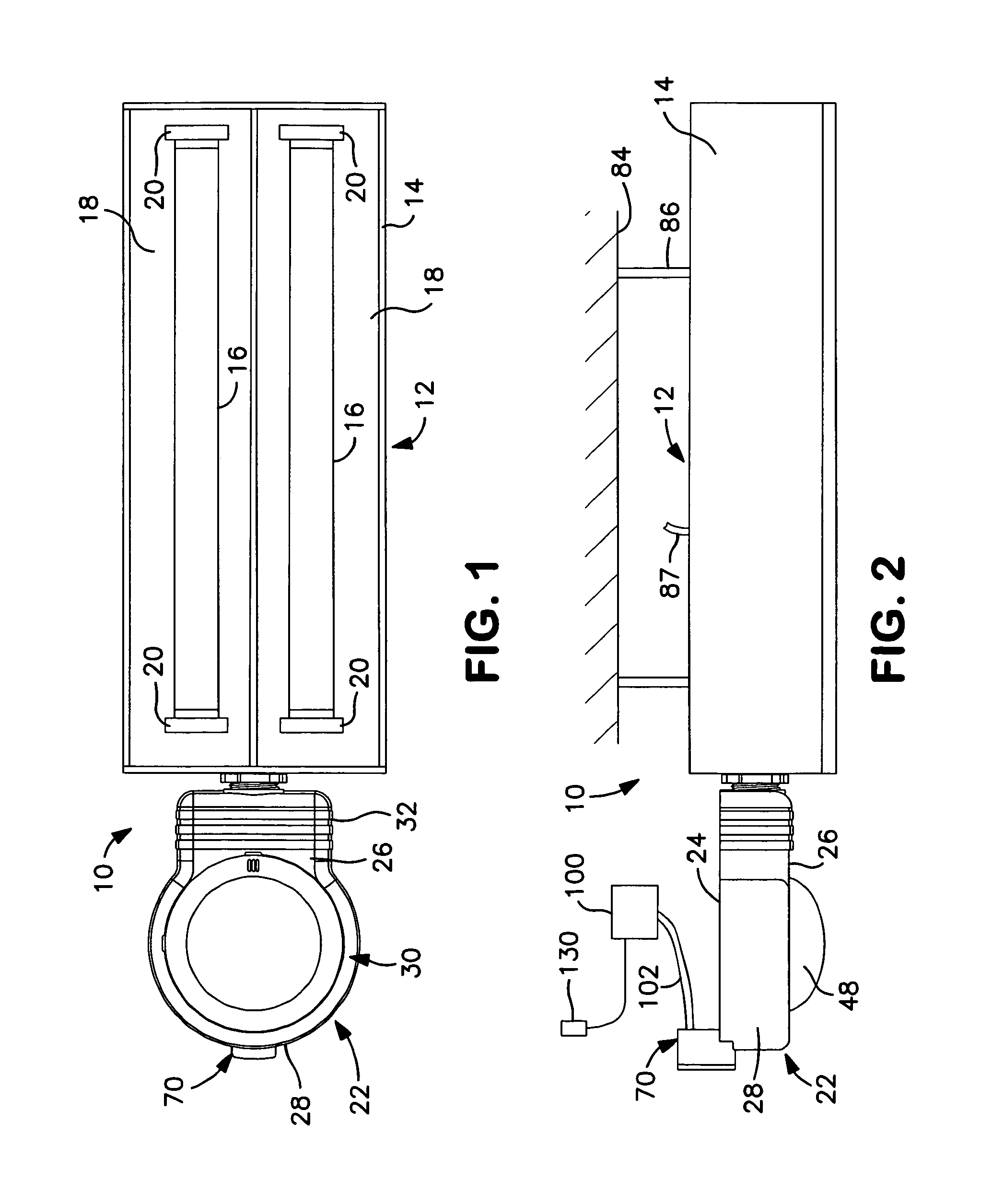
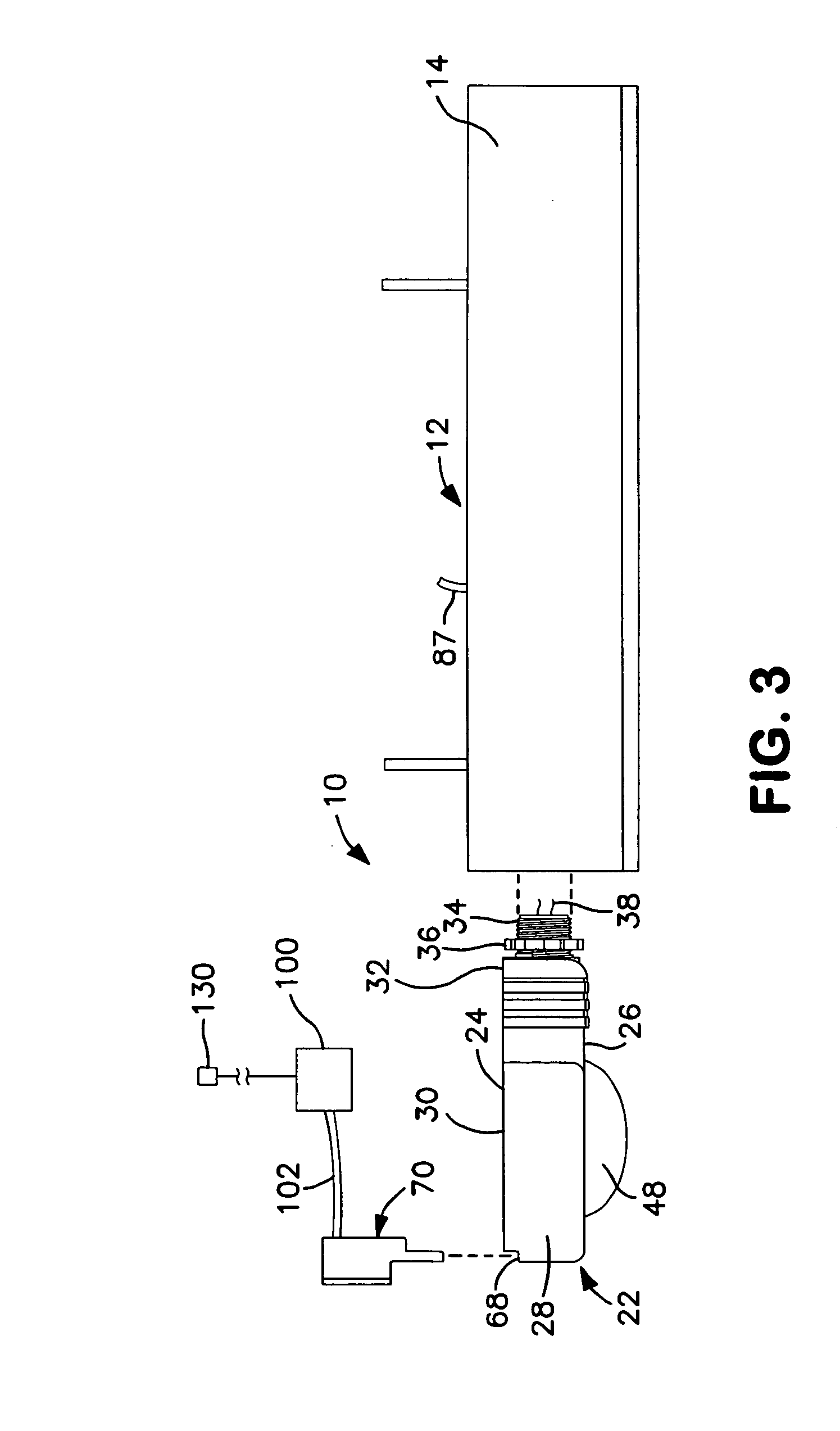
[0043]The present invention is directed to an occupancy sensor which can be used alone to control and / or override the operation of an electrical system, or used with a separate override unit to control the operation of the occupancy sensor. The occupancy sensor, in accordance with illustrative embodiments of the present invention, is provided with a light sensor which may be used in conjunction with a separate override unit. The override unit can be connected to the occupancy sensor when desired depending on the requirements for the specific environment of the installation. The override unit may be added to an installation at a later time without replacing or altering the wiring of the occupancy sensor. The occupancy sensor, in accordance with illustrative embodiments of the present invention, is operatively connected to an electrical system such as a light assembly, fan, alarm system, heating, ventilation and / or air conditioning (HVAC) system or other load and can control the load....


PUM


Abstract

An occupancy sensor is provided with a separable override unit which can selectively override the operation of the occupancy sensor at designated times and for selected time intervals. The occupancy sensor includes a light sensor for actuating the occupancy sensor and a light assembly when the ambient light is below a predetermined level and to deactivate the occupancy sensor when the ambient light is above a threshold level to prevent the light assembly from being actuated when the light level is sufficient to avoid the need for actuating the light assembly. The override unit is removably attached to the occupancy sensor and is provided with a light source, such as an LED. The override unit is coupled to the occupancy sensor to emit light to actuate the light sensor of the occupancy sensor, thereby controlling the operation of the occupancy sensor, such as by preventing the occupancy sensor from being actuated regardless of the light level in the surrounding areas. The occupancy sensor includes a cavity on a top surface for receiving the override unit. The light sensor of the occupancy sensor is positioned in the cavity. The LED on the override unit is on an end that is inserted into the cavity to align with the light sensor. A control unit is operatively connected to one or more override units for selectively controlling the normal operation of the occupancy sensor.

Description

CROSS-REFERENCE TO RELATED APPLICATIONS[0001]Related subject matter is disclosed in co-pending U.S. patent application of Jonathan Williams et al, Ser. No. 29 / 309,182, filed Jul. 1, 2008, entitled “Occupancy Sensor”; and in co-pending U.S. patent application of Jonathan Williams et al, Ser. No. 11 / 138,084, filed May 27, 2005 (now issued as U.S. Pat. No. 7,432,690); the entire contents of each of these applications being expressly incorporated herein by reference.FIELD OF THE INVENTION[0002]The present invention is directed to an occupancy sensor / load controller for sensing the presence of a person in a designated area and for actuating an electrical load or system and, in the case of a lighting fixture load, having the ability to operate the lighting fixture at more than one light level. More particularly, the present invention is directed to a load controller having an occupancy sensor, one or more load control outputs, and a photosensor that is operable in conjunction with an over...

Claims


Application Information

Patent Timeline
IPC IPC(8): H05B37/02G01J1/42
CPCG01J1/04G01J1/0403G01J1/0448G01J1/4204G01J5/0022G01J5/0025H05B37/0209G01J5/084G01J5/0896H05B33/0854H05B37/0218H05B37/0227Y02B20/46G01J5/08H05B47/11Y02B20/40H05B47/115H05B47/17H05B47/10H05B45/10
Inventor WILLIAMS, JONATHAN D.HARTNAGEL, THOMAS J.MARTIN, ROBERT A.BENDER, R. KURT
Owner HUBBELL LIGHTING INC
Why Eureka
Try Eureka