
Light emitting device with collimating structure

Inactive Publication Date: 2010-11-25
KONINKLIJKE PHILIPS ELECTRONICS NV
View PDF9 Cites 6 Cited by
  • Summary
  • Abstract
  • Description
  • Claims
  • Application Information

AI Technical Summary

Benefits of technology

[0011]One object of the present invention is to at least partly overcome this problem, and to provide a collimating device that can collimate light from a multi-LED lighting unit and that provides a good color mixing of the collimated light.

Problems solved by technology

However, since the LEDs are positioned in different positions in respect to the collimator, the color mixing is far from perfect, and the position of the LEDs in the collimator will lead to noticeable differently colored regions in the far field spot.
However, the photo mixing material will reduce the light utilization efficiency, since it will prevent at least part of the light emitted from exiting the funnel, by means of for example absorption of light and reflection back towards the LEDs.
Further, the scattering material in the collimating funnel, especially close to the output opening, will negatively affect the collimation obtainable by the device.

Method used


Image

  • Light emitting device with collimating structure
  • Light emitting device with collimating structure
  • Light emitting device with collimating structure

Examples


Embodiment Construction

[0043]The present invention relates in part to a light emitting device comprising a lighting unit and a collimating structure arranged to receive and collimate the light emitted by the lighting unit. The collimating structure it self forms an especially contemplated aspect of the present invention, even though it is herein below described as a component of a light emitting device.

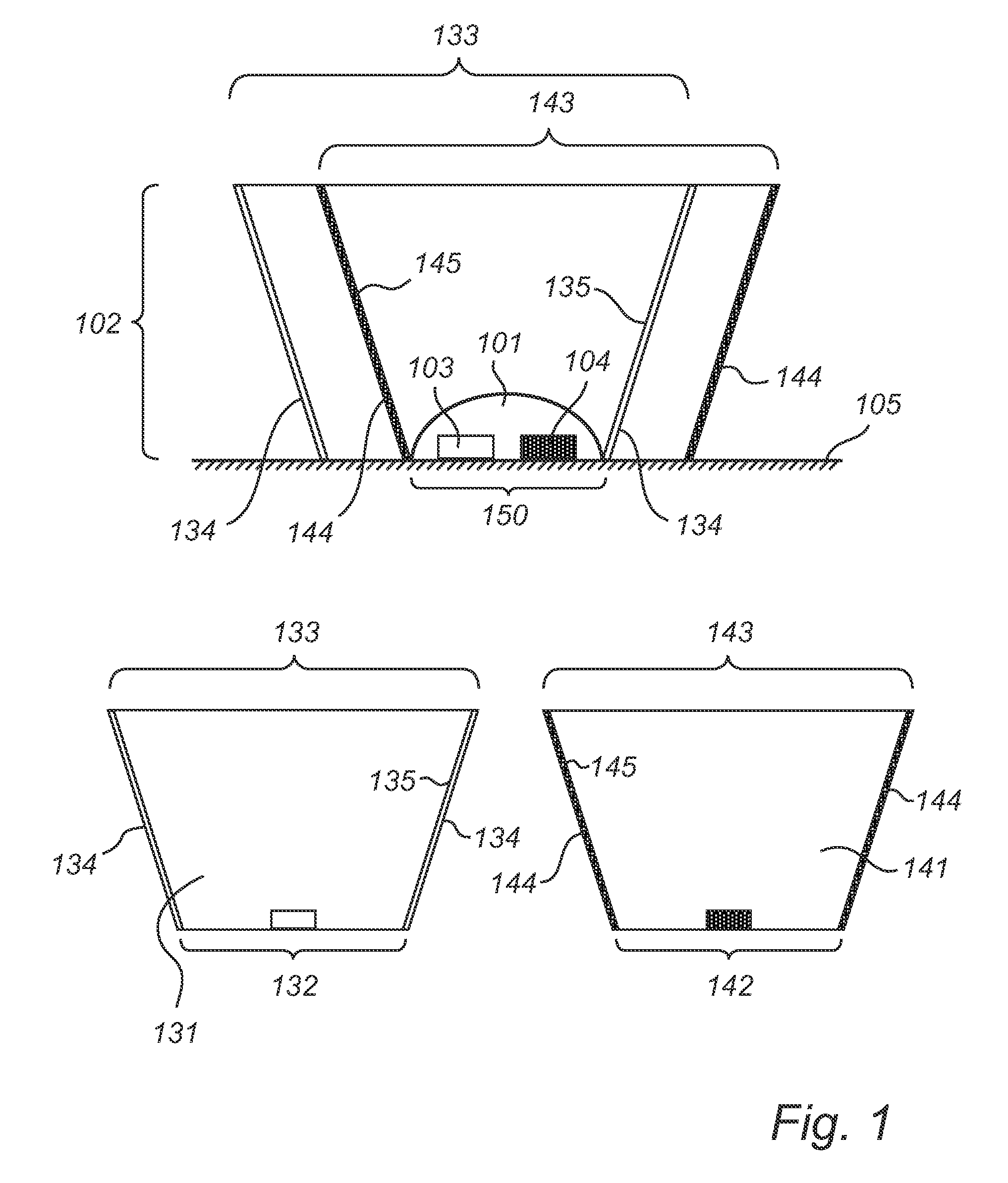
[0044]A first exemplary embodiment of a light-emitting device of the present invention is illustrated in cross-sectional view in FIG. 1.

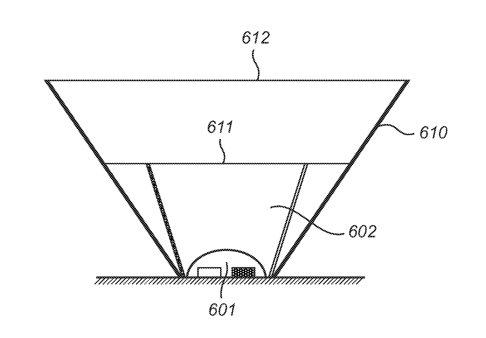
[0045]The light-emitting device comprises a lighting unit 101 on which a light collimating structure 102 is arranged.

[0046]The lighting unit 101 comprises a first light emitting diode (LED) 103 capable of emitting light of a first wavelength interval, e.g. light of a first color, and a second light emitting diode 104 capable of emitting light of a second wavelength interval, e.g. light of a second color.

[0047]As used herein, “light-emitting diodes” relates to all different ...


PUM


Abstract

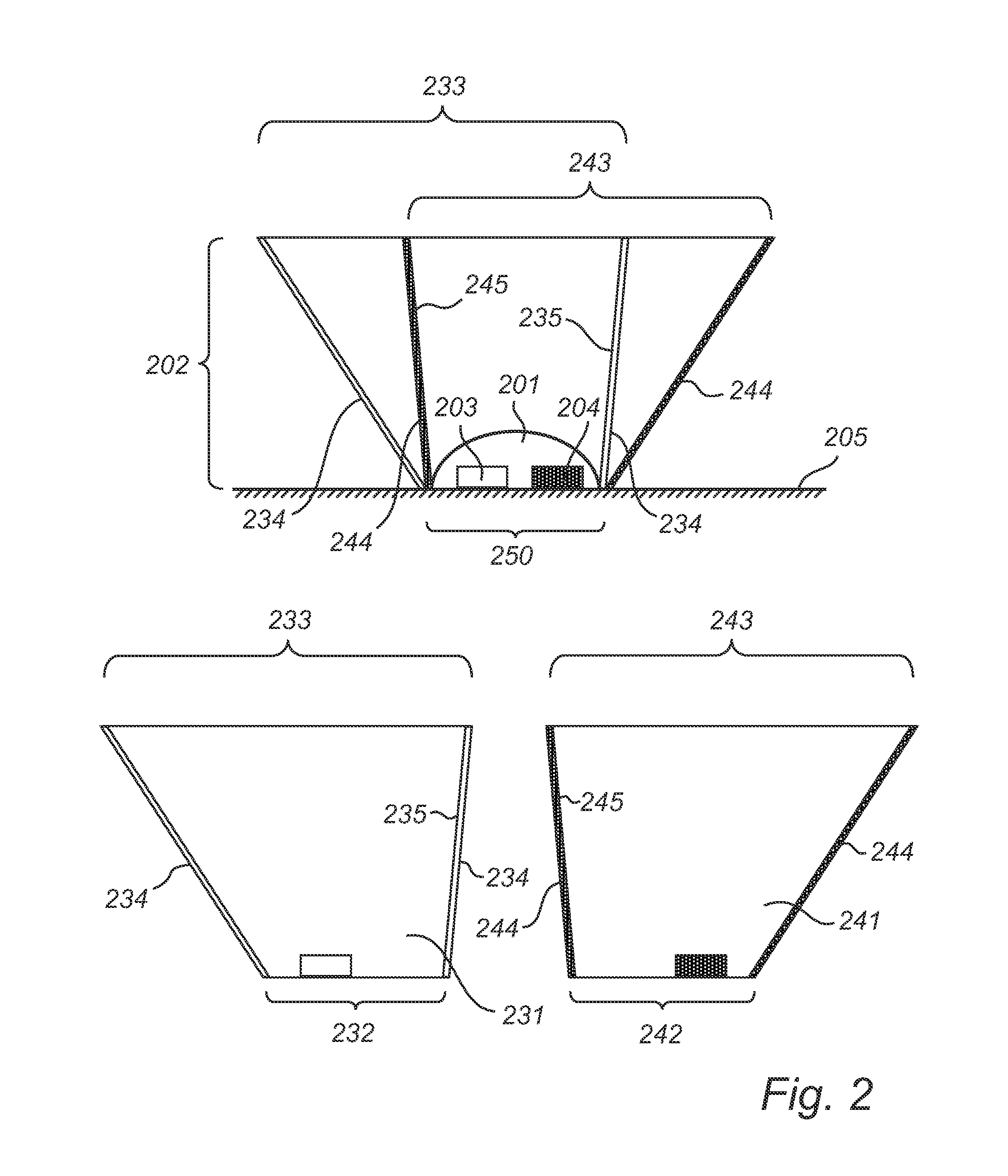
The present invention provides a light collimating structure (102) comprising a first collimator (131) collimating light of a first property and at least one second collimator (141) collimating light of a second property, where the receiving areas (132, 142) of the collimators at least partly overlap and where the output areas (133, 143) of the collimators partly overlap. The at least two collimators act essentially independently from each other. Hence, the collimators can be positioned independently from each other, in order to provide good collimation for each of the light sources of the lighting unit. Further, the collimators may be designed independently from each other such that a good light mixing is obtained.

Description

FIELD OF THE INVENTION[0001]The present invention relates to a light collimating structure, as well as to a light-emitting device comprising a lighting unit with such a light collimating structure arranged to receive and collimate light emitted by the lighting unit.BACKGROUND OF THE INVENTION[0002]Recently, much progress has been made in increasing the brightness of light emitting diodes (LEDs). As a result, it is anticipated that LEDs, in the coming years, will become sufficiently bright and inexpensive to serve as light sources in lamps with adjustable color, backlights for liquid crystal displays, front and rear projection displays and projectors that generate light patterns.[0003]For many of these applications, it is desired that the light sources emit collimated light, where the beam shape and color can be set. Furthermore, the colors should be well mixed.[0004]Color variability is conventionally obtained by grouping several LEDs of different colors into one lighting unit, a pi...

Claims


Application Information

Patent Timeline
IPC IPC(8): H01L33/58G02B27/30H01L33/60
CPCF21Y2101/02F21Y2113/005G02B27/30G02B19/0028H01L33/60G02B19/0066H01L25/0753F21V17/02F21Y2113/13F21Y2115/10H01L2924/0002H01L2924/00
Inventor VISSENBERG, MICHEL CORNELIS JOSEPHUS MARIEVAN GORKOM, RAMON PASCAL
Owner KONINKLIJKE PHILIPS ELECTRONICS NV
Learn More