
Light control system and control method thereof

Inactive Publication Date: 2010-11-25
PIXART IMAGING INC
View PDF54 Cites 26 Cited by
  • Summary
  • Abstract
  • Description
  • Claims
  • Application Information

AI Technical Summary

Benefits of technology

[0008]The present invention provides a light control system, in which no physical control line needs to be constructed during installation so as to simplify the installation procedure and to reduce the system cost.
[0009]The present invention provides a light control system, wherein each illumination module may be manufactured as an individual one so as to simplify the maintenance and replacement thereof.
[0010]The present invention provides a light control system, wherein each illumination module may be manufactured as an individual one and it is not necessary to construct physical control lines during installation thereby having higher expandability.
[0011]The present invention provides a control method of a light control system, wherein a plurality of illumination modules may be controlled by a single remote controller so as to simplify the operating procedure of the light control system.
[0012]The present invention provides a control method of a light control system, wherein a remote controller may be used to simultaneously control the ON / OFF of a part of a plurality of illumination modules according to actual requirement thereby having higher operating flexibility.
[0020]In the light control system and control method thereof, the ON / OFF of one or a plurality of illumination modules may be controlled by pressing at least one button on the remote controller. When it is desired to simultaneously control the ON / OFF of a plurality of illumination modules, a selected set of illumination modules may be turned on or turned off simultaneously. For example, when the button is pressed the first time, a set of illumination modules may be turned on or turned off together; and when the button is pressed the second time (pressed again), another set of illumination modules may be turned on or turned off together. In this manner, the practicability of the light control system of the present invention can be increased significantly.

Problems solved by technology

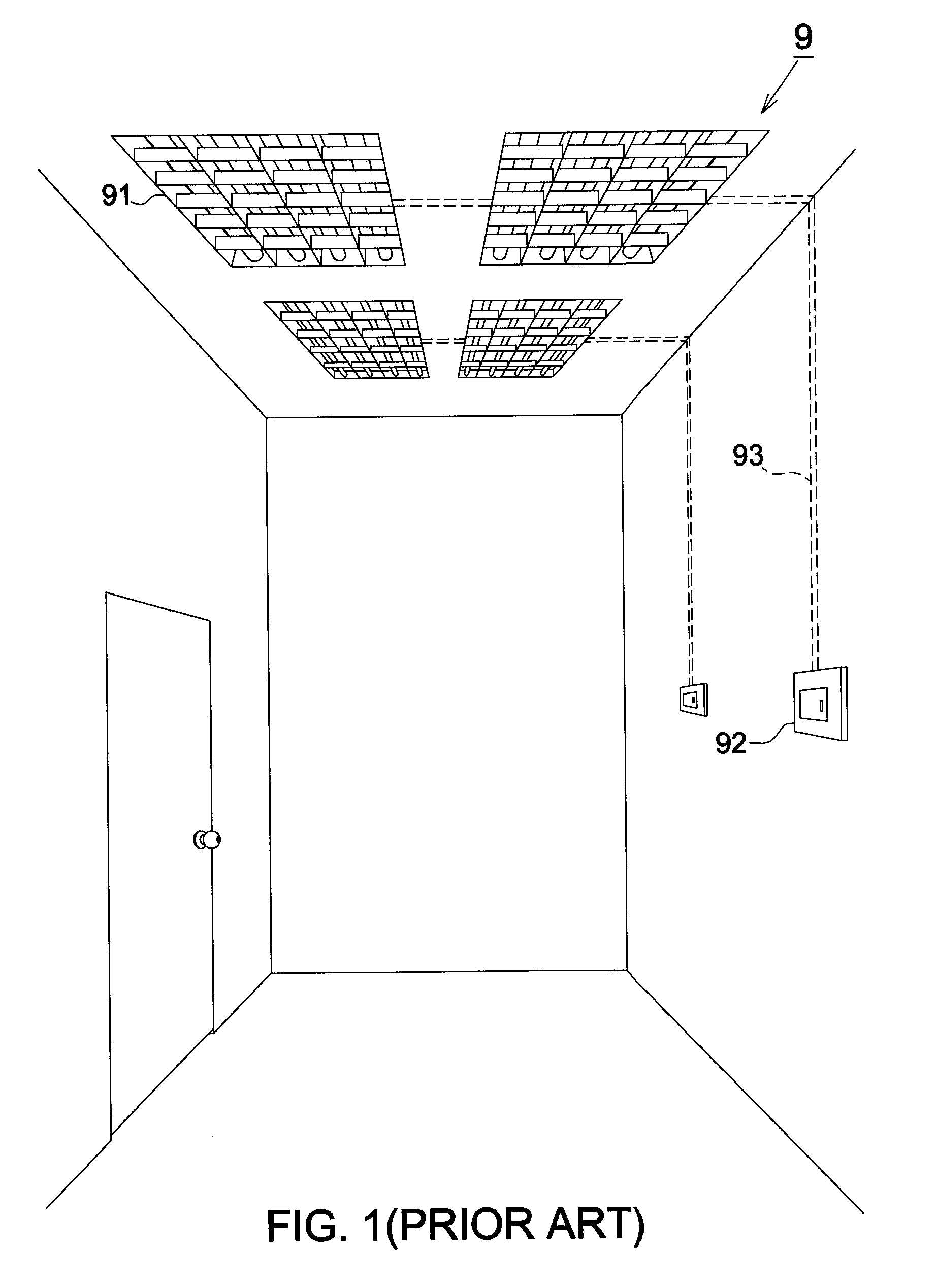
However, as the mechanical switch 92 is generally installed on the surface of wall, not only the eye is offended but poor contact occurs due to frequent operation such that the mechanical switch 92 needs to be replaced from time to time.
In addition, the wall surface around the switch is frequently touched when a user switches the mechanical switch 92 such that the wall is easily smudged and needs to be cleaned frequently.
Furthermore, since the control line 93 has to be installed under the wall surface, not only higher cost is required during installation but the maintenance and replacement of the control line 93 will take more money and time.
However, the operating complexity and installation cost will be significantly increased.

Method used


Image

  • Light control system and control method thereof
  • Light control system and control method thereof
  • Light control system and control method thereof

Examples


Embodiment Construction

[0033]It should be noticed that, wherever possible, the same reference numbers will be used throughout the drawings to refer to the same or like parts.

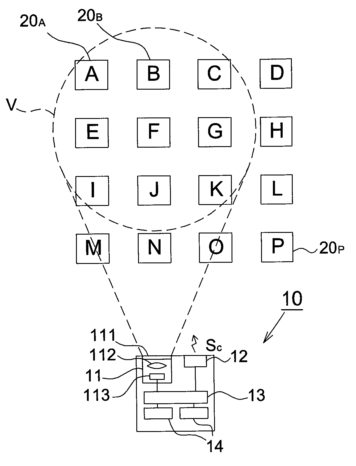
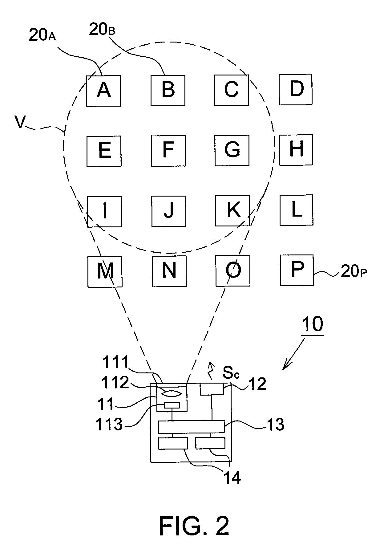
[0034]Please refer to FIG. 2, it shows a schematic diagram of the light control system according to an embodiment of the present invention. The light control system includes a remote controller 10 and a plurality of illumination modules 20, e.g. illumination modules 20A˜20P. The remote controller 10 is configured to control the ON / OFF of the light source included in one or a part of the illumination modules 20.

[0035]The remote controller 10 includes an image sensing module 11, a transmitter 12, a processing unit 13 and at least one button 14, wherein the processing unit 13 is coupled to the image sensing module 11, the transmitter 12 and the button 14. The image sensing module 11 is configured to acquire images of an identification signal emitted from the illumination modules 20. The transmitter 12 is configured to send a wireless con...


PUM


Abstract

A light control system includes at least one illumination module and a remote controller. Each illumination module includes an identification signal generator, at least one light source, a receiving unit and a control circuit. When the receiving unit receives a first wireless control signal, the control circuit controls the identification signal generator to emit an identification signal; when the receiving unit receives a second wireless control signal, the control circuit controls the ON / OFF of the light source. The remote controller sends the first and second wireless control signals to the illumination module, acquires the identification signal emitted from the identification signal generator to generate a plurality of images, and identifies the illumination module according to the images. The present invention further provides a control method of a light control system.

Description

CROSS REFERENCE TO RELATED APPLICATION[0001]This application claims the priority benefit of Taiwan Patent Application Serial Number 098116678, filed on May 20, 2009, the full disclosure of which is incorporated herein by reference.BACKGROUND[0002]1. Field of the Invention[0003]This invention generally relates to a light control system and a control method thereof and, more particularly, to a light control system incorporating an image sensor and a control method thereof.[0004]2. Description of the Related Art[0005]Please refer to FIG. 1, it shows a conventional indoor light control system 9. The light control system 9 includes at least one lamp 91 and at least one mechanical switch 92, wherein each mechanical switch 92 is electrically connected to at least one lamp 91 through a control line 93 so as to control the ON / OFF of the lamp 91.[0006]However, as the mechanical switch 92 is generally installed on the surface of wall, not only the eye is offended but poor contact occurs due to...

Claims


Application Information

Patent Timeline
IPC IPC(8): H05B37/02
CPCH05B37/029H05B37/0272H05B47/155H05B47/19
Inventor LU, CHIH HUNGLIN, CHO YI
Owner PIXART IMAGING INC
Learn More