Array antenna, tag communication device, tag communication system, and beam control method for array antenna

a technology of array antennas and beam control methods, applied in individual energised antenna arrays, resonant antennas, radiating elements structural forms, etc., can solve the problems of significant deformation of the accuracy of movement direction detection, side lobe and grating lobe, and inability to obtain lines, etc., to reduce the grating lobe and the side lobe

Active Publication Date: 2010-11-25
ORMON CORP
View PDF6 Cites 14 Cited by
  • Summary
  • Abstract
  • Description
  • Claims
  • Application Information

AI Technical Summary

Benefits of technology

[0025]According to the present invention described above, in an array antenna in which a directivity direction of a beam of a radio wave is electrically controllable, the array antenna including a second antenna element and a third antenna element, which are arranged spaced apart on a first virtual line, and a first antenna element and a fourth antenna element, which are arranged spaced apart on a second virtual

Problems solved by technology

However, the applicant found through experiments that a new problem arises if the number of antenna elements is 2×2=4 elements.
The new problem includes the problems of a side lobe and a grating lobe.
It is apparent through th

Method used


Image

  • Array antenna, tag communication device, tag communication system, and beam control method for array antenna
  • Array antenna, tag communication device, tag communication system, and beam control method for array antenna
  • Array antenna, tag communication device, tag communication system, and beam control method for array antenna

Examples


Embodiment Construction

[0035]The best modes for carrying out the invention will be described in detail below with reference to the accompanied drawings.

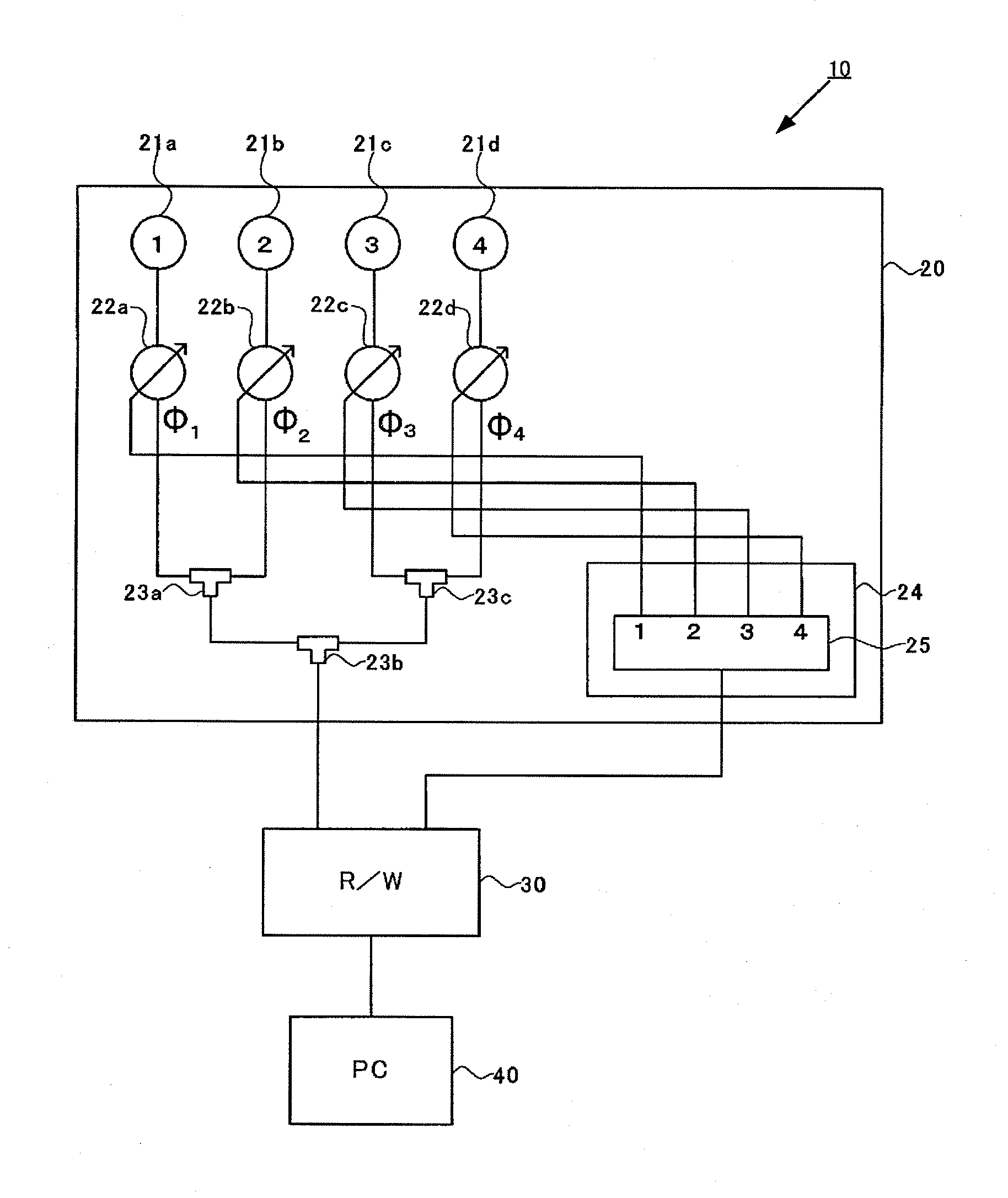
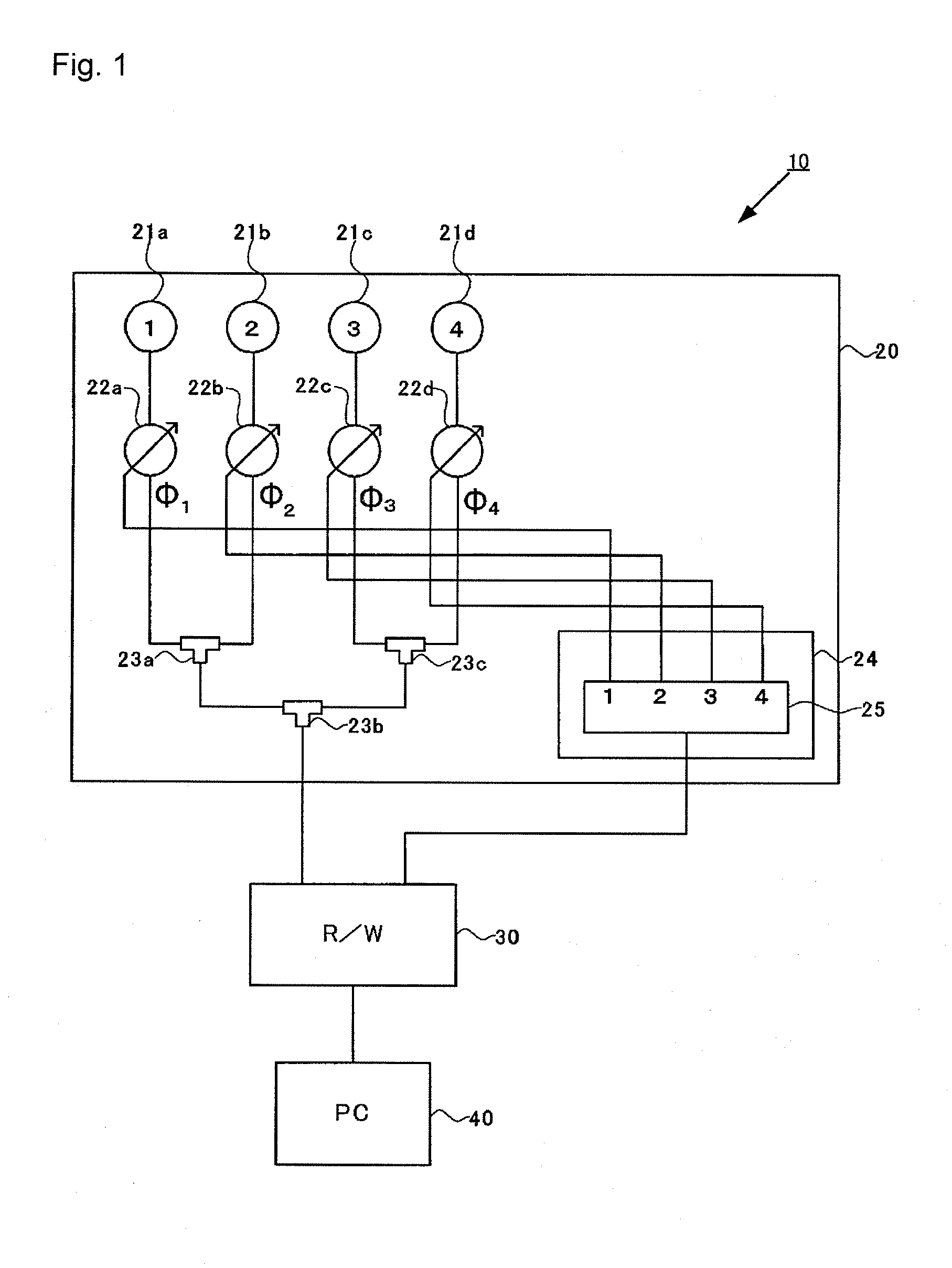
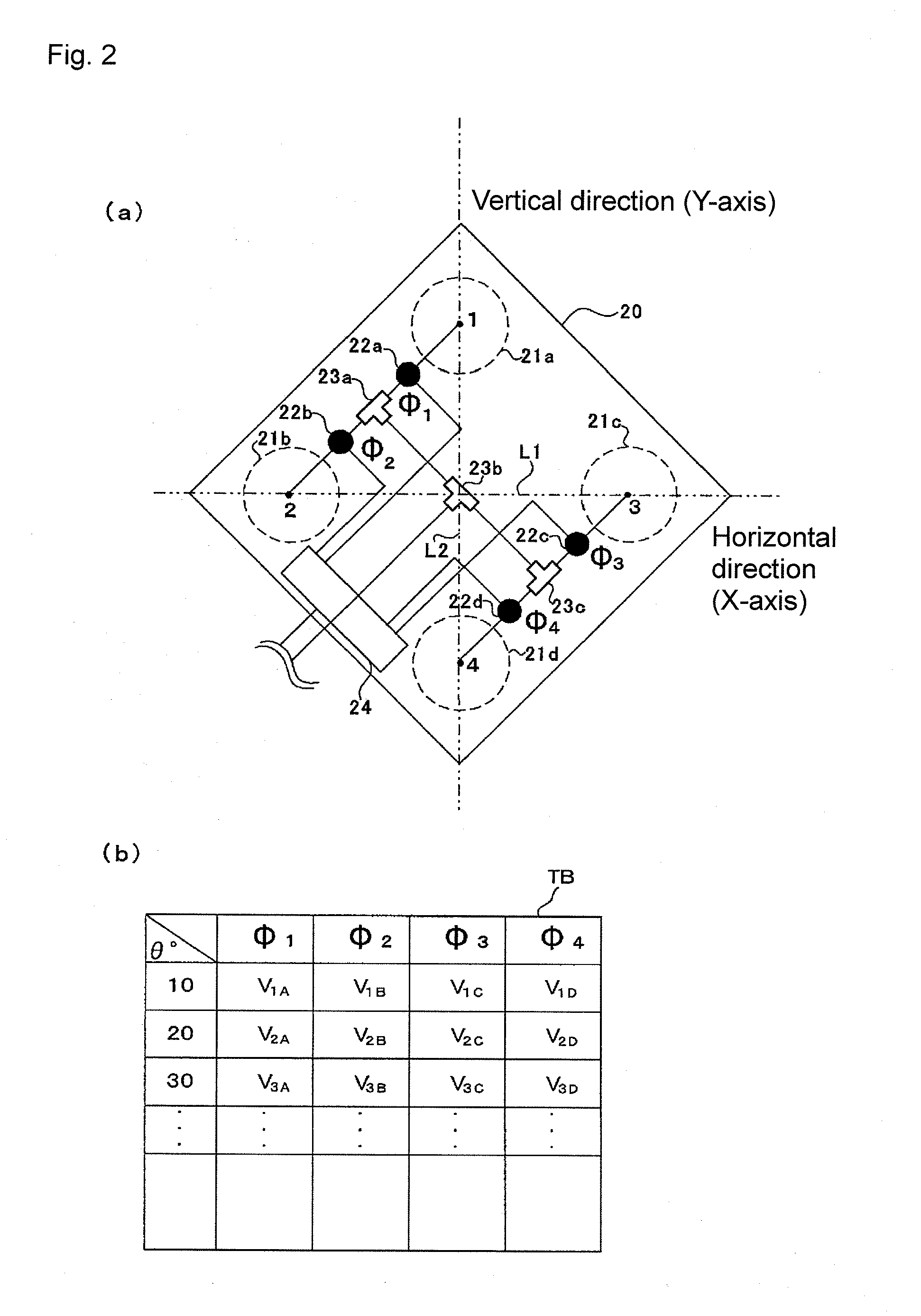
[0036]FIG. 1 is a block diagram schematically showing a schematic configuration of a tag communication system of the present invention; FIG. 2(a) is a plan view of the schematic configuration of an array antenna of the present invention seen from a back surface side, and FIG. 2(b) is an internal table stored in a controller; FIG. 3 is a schematic view describing a directivity direction of the array antenna of the present invention; FIGS. 4(a) and 4(b) are conceptual views for describing a principle of a feeding phase to each antenna element of the array antenna of the present invention; FIG. 5 is a conceptual view for describing the principle of the feeding phase to each antenna element of the array antenna of the present invention; and FIG. 6 is a graph showing a reduction effect of a side lobe in the array antenna of the present invention.

[0037]As shown ...


PUM


Abstract

Provided are an array antenna capable of miniaturizing an array antenna while reducing side lobes, a tag communication device and tag communication system provided with the array antenna, and a beam control method for the array antenna. When XY coordinates and a feeding phase of each antenna element (21a to 21d) are defined as the antenna element (21a) (0, Y1)·φ1, the antenna element (21b) (−X1, 0)·φ2, the antenna element (21c) (X2, 0)·φ3, the antenna element (21d) (0, −Y2)·φ4, wavelengths of λ, and directivity directions of θ, each of the feeding phases is set so that the following conditional equations φ1=φ4, φ2=2π·X1·sin(θ)/λ+φ1, φ3=φ1−2π·X2·sin(θ)/λ are all satisfied.

Description

TECHNICAL FIELD[0001]The present invention relates to an array antenna in which a direction of a beam of a radio wave can be varied, a tag communication device and a tag communication system including the array antenna, and a beam control method for the array antenna.BACKGROUND ART[0002]An array antenna is conventionally known as one of directivity antennas. The array antenna has a plurality of arrayed antenna elements, and can electronically change a directivity direction of a beam of a radio wave while controlling a phase of a signal flowing to each antenna element. Since the directivity direction of the beam of the radio wave can be varied by changing a feeding phase of each antenna element, a communication region can be enlarged by scanning the beam of the radio wave as in a tag communication antenna described in Patent Document 1, or use can be made in detection of a tag movement direction as in a tag movement direction detection system described in Patent Document 2. A case in...

Claims


Application Information

Patent Timeline
IPC IPC(8): H01Q3/30H01Q1/38H01Q21/06
CPCH01Q1/2216H01Q21/065H01Q3/385
Inventor NOGAMI, HIDEKATSU
Owner ORMON CORP
Why Eureka
Try Eureka