Multi-core processor system
a processor and core technology, applied in the field of multi-core processor systems, can solve problems such as cost increas
- Summary
- Abstract
- Description
- Claims
- Application Information
AI Technical Summary
Benefits of technology
Problems solved by technology
Method used
Image
Examples
first embodiment
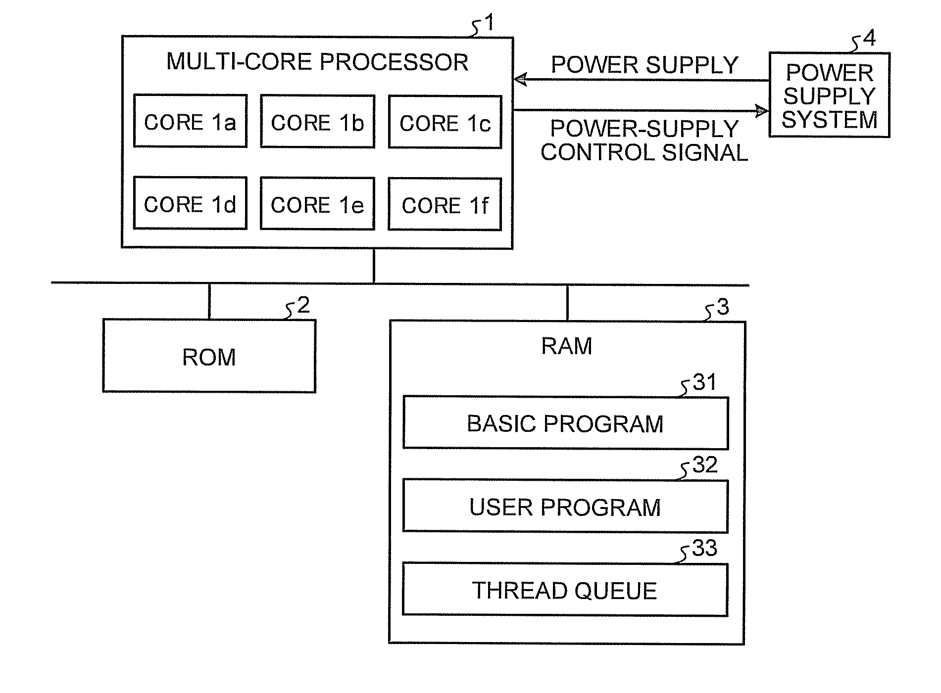
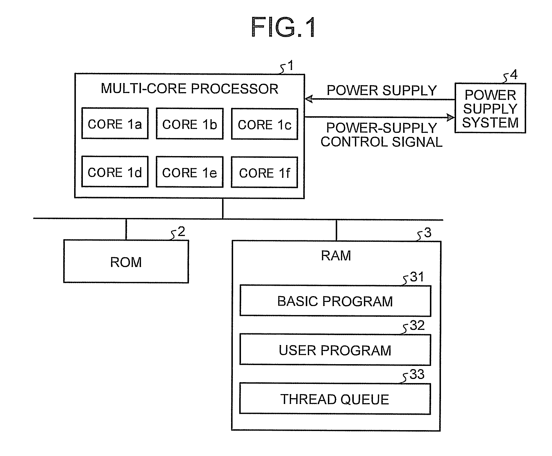
[0051]As explained above, each of the processor cores includes the power-supply stopping means for causing, when the number of standby threads is zero, the power supply system 4 to stop power supply to the processor and the power-supply resuming means for causing, when the number of standby threads exceeds zero, the power supply system 4 to resume power supply to the other stopped processor cores. This makes it possible to turn on and off power supplied to the processor cores according to a load state without preparing a processor and hardware exclusively used for power supply control.
[0052]According to the first embodiment, rather than the user program, the basic program generates the power-supply stopping means and the power-supply resuming means. Therefore, a user can avoid the necessity of describing processing for turning on and off the processor core power supplies in the user program.
[0053]According to the configuration of the first embodiment, in the power-supply-resumption...
second embodiment
[0057]FIGS. 9A to 9C are flowcharts for explaining the operation of the multi-core processor system according to the The processor cores 1a to 1f can execute the same operation. Therefore, only the operation of the processor core 1a is explained below as a representative of the operation of the processor cores 1a to 1f.
[0058]As shown in FIG. 9A, first, the basic control means 101a determines whether the application task is allocated to the processor core 1a (S201). When the application task is allocated (“Yes” at S201), the basic control means 101a executes the application task (S202). When the application task is executed, the processor core 1a generates a thread. When the processor core 1a ends the execution of the application task, the operation shifts to S201.
[0059]When it is determined that the application task is not allocated (“No” at S201), the basic control means 101a starts and executes the thread control task (S203). The thread control task determines, referring to the ...
third embodiment
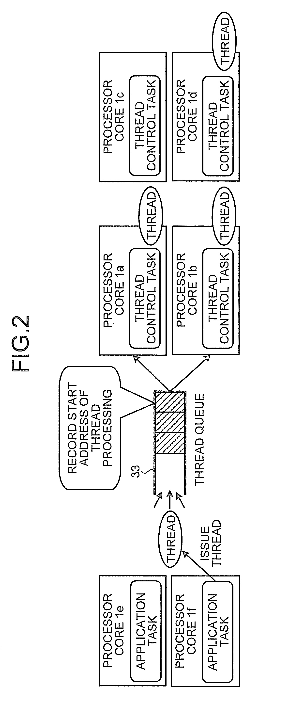
[0067]FIG. 10 is a schematic diagram for explaining characteristics of a multi-core processor system according to the The processor cores 1e and 1f are executing the application task, respectively generate threads based on the application task, and add the generated threads to the thread queue 33. The processor cores 1a to 1d are executing the thread control task. The processor cores 1a to 1d extract threads from the thread queue 33 and execute the threads. Two kinds of thresholds (thresholds A and B) are set concerning the number of threads put on standby in the thread queue 33. The thread control task turns off a power supply for an own processor core when the number of standby threads does not exceeds the threshold A. Even when the number of standby threads does not exceed the threshold A, when the number of standby threads is equal to or larger than one and no other processor core is executing a thread, as exceptional processing, the thread control task does not turn off the po...
PUM
 Abstract
Description
Claims
Application Information
 - R&D
- Intellectual Property
- Life Sciences
- Materials
- Tech Scout
- Unparalleled Data Quality
- Higher Quality Content
- 60% Fewer Hallucinations
Browse by: Latest US Patents, China's latest patents, Technical Efficacy Thesaurus, Application Domain, Technology Topic, Popular Technical Reports.
© 2025 PatSnap. All rights reserved.Legal|Privacy policy|Modern Slavery Act Transparency Statement|Sitemap|About US| Contact US: help@patsnap.com


