Apparatus and method of forming the brake actuator

Inactive Publication Date: 2010-12-02
INDIAN HEAD INDUSTRIES INC
View PDF39 Cites 6 Cited by
  • Summary
  • Abstract
  • Description
  • Claims
  • Application Information

AI Technical Summary

Benefits of technology

[0015]An advantage of the present invention is to provide an improved apparatus and method for installing a seal into a seal groove defined in a flange case thereby eliminating need for manual installation.
[0016]Another advantage of the present invention is to provide an improved apparatus and method for installing the seal into the seal groove that is not cost effective and eliminates likelihood of human error.
[0017]Still another advantage of the present invention

Problems solved by technology

Manual installation of the seals is not cost effective and presents a high likelihood of human error.
This method negatively impacts formation of perfect “seat contact” between the sea

Method used


Image

  • Apparatus and method of forming the brake actuator
  • Apparatus and method of forming the brake actuator
  • Apparatus and method of forming the brake actuator

Examples


Embodiment Construction

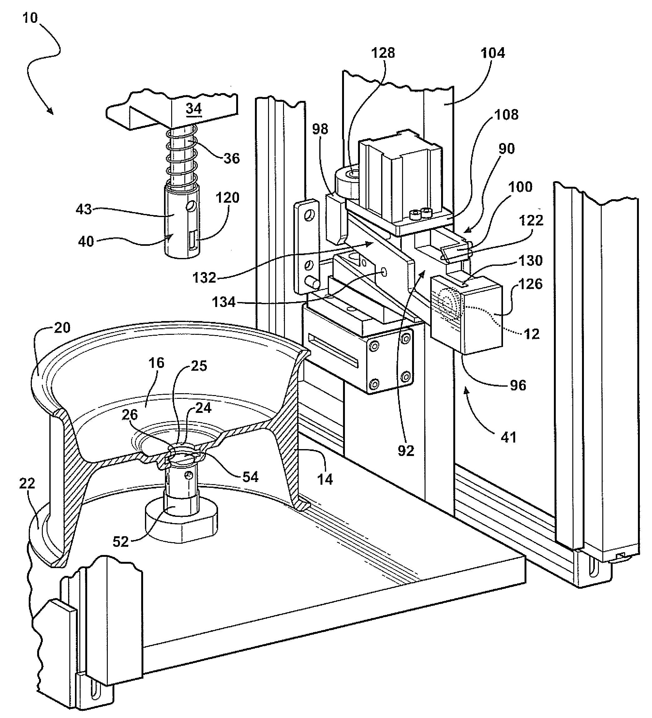
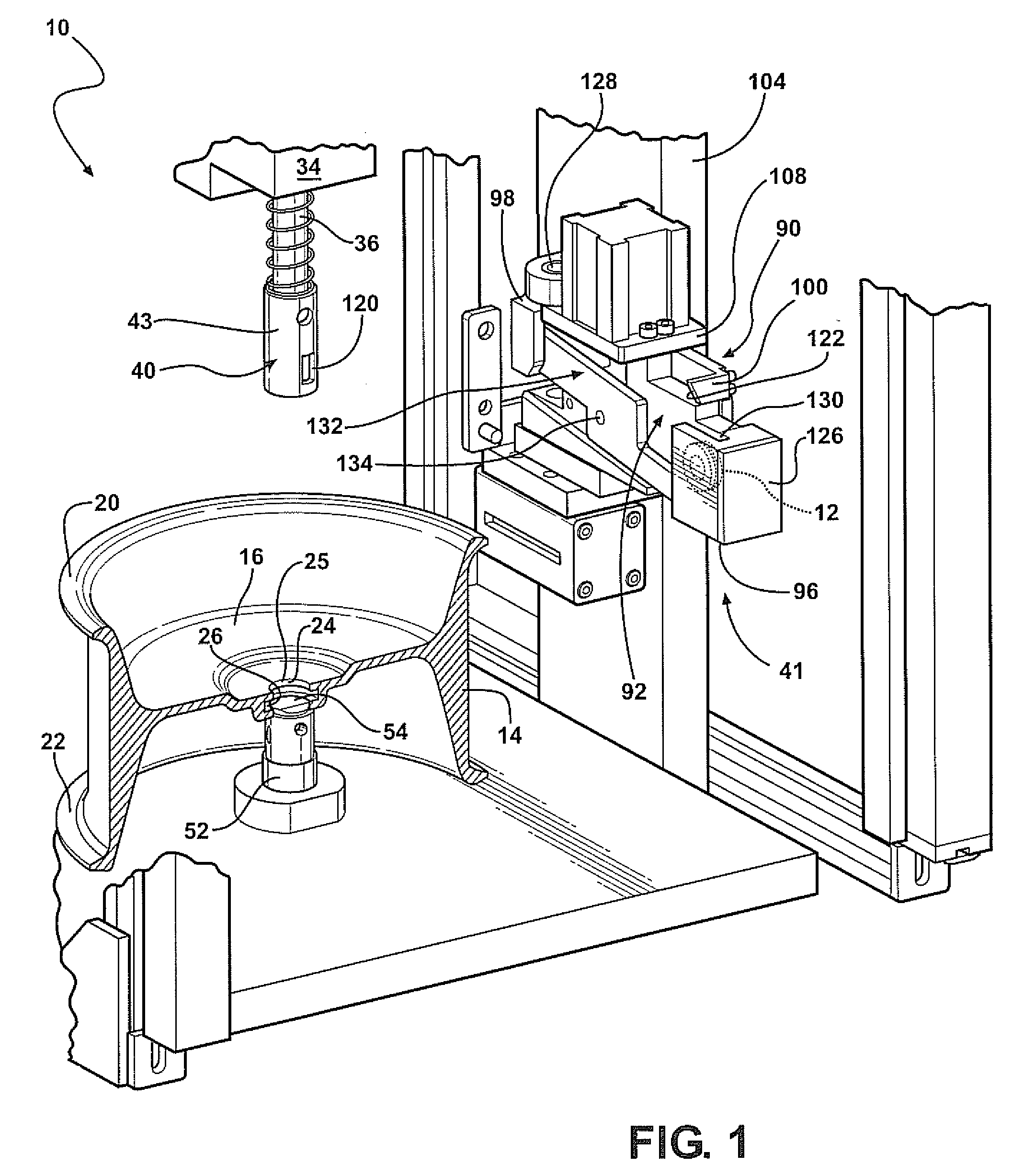
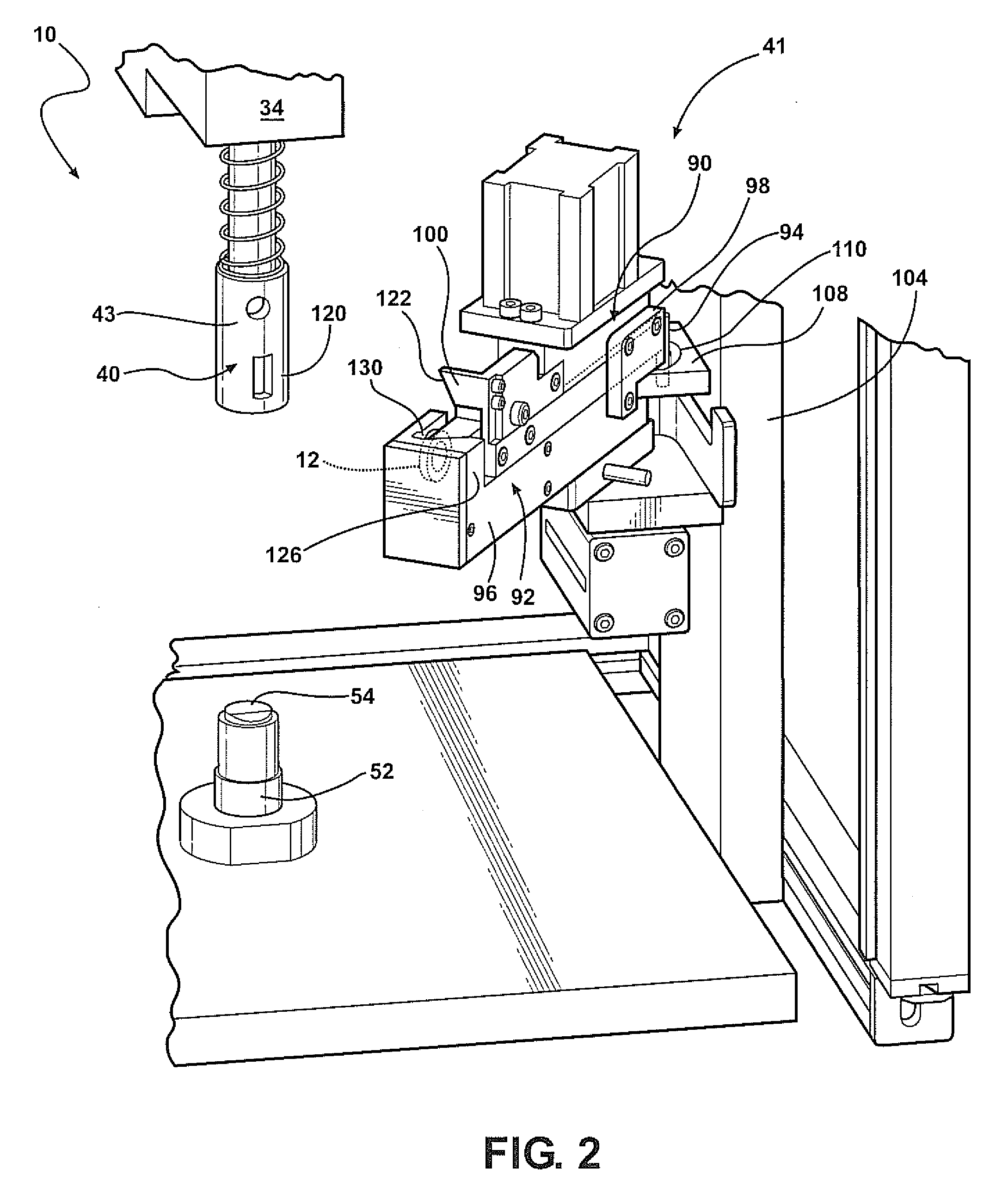
[0031]Referring to the Figures, wherein like numerals indicate like or corresponding parts, an apparatus of the present invention is generally shown at 10. The apparatus 10 installs a seal 12 into a generally H-shaped flange case, generally indicated at 14, of a brake actuator (not shown). However, it should be understood to those of skill in the art that other case configuration requiring a seal are also contemplated by the inventor. The flange case 14 includes a central web portion 16, an outer wall or peripheral wall 18 and radially extending flanges 20 and 22. The brake actuator also includes other components (not shown) required to actuate the brake. A cover or head portion of the brake actuator includes an end wall, a side wall and a flange or skirt portion. A flexible diaphragm extends between the flange case and the cover thereby forming a lower pneumatic chamber and an upper pneumatic chamber on opposed sides of the diaphragm.

[0032]The flange case 14 defines an opening or a...


PUM

PropertyMeasurementUnit
Diameteraaaaaaaaaa

Abstract

A apparatus for forming a brake actuator that includes a flange case defining a peripheral groove circumscribing a push rod movable axially in relation to the flange case whereby the push rod presents a push rod guide bushing on the bearing surfaces of the push rod guide bushing being in contact with a seal. An automatic manipulator of the apparatus moves in multi-axial directions relative the flange case. A tucking tool of the automatic manipulator holds the seal. The tool includes at least two members movable relative to one another. First member rotates around the axis of the tucking tool and presents a tucking surface for forcing the seal into the peripheral groove of the flange case. Second member gradually injects the seal into the peripheral groove and pushed the seal into the back wall of the peripheral groove.

Description

FIELD OF THE INVENTION[0001]The present invention relates to an improved diaphragm-type pneumatic brake actuator for vehicle braking apparatus and more particularly to a method of installing a seal into a flange case of the brake actuator.BACKGROUND OF THE INVENTION[0002]Pneumatic brake actuators form part of the pneumatic braking apparatus of commercial vehicles having a large gross vehicle weight, including trucks, buses and trailers requiring a braking apparatus which responds rapidly with substantial braking power. A typical diaphragm-type pneumatic brake actuator includes a housing having cup-shaped housing members including opposed rim or flange portions, a flexible diaphragm which is cup-shaped in its relaxed condition including a central portion, a generally conical side wall which surrounds the central portion and a generally radial rim portion which extends between the rim portions of the housing members. A brake actuator further includes a piston having a contact surface ...

Claims


Application Information

Patent Timeline
IPC IPC(8): B23P11/02B23P19/02
CPCB23P19/084F16D2125/04Y10T29/53657F16D2250/0092Y10T29/49863F16D2250/00
Inventor OSTER, WAYNE HYDE
Owner INDIAN HEAD INDUSTRIES INC
Why Eureka
Try Eureka