
Multi-cage spacer

Inactive Publication Date: 2010-12-02
FORTERRA CONCRETE PROD INC +1
View PDF11 Cites 10 Cited by
  • Summary
  • Abstract
  • Description
  • Claims
  • Application Information

AI Technical Summary

Benefits of technology

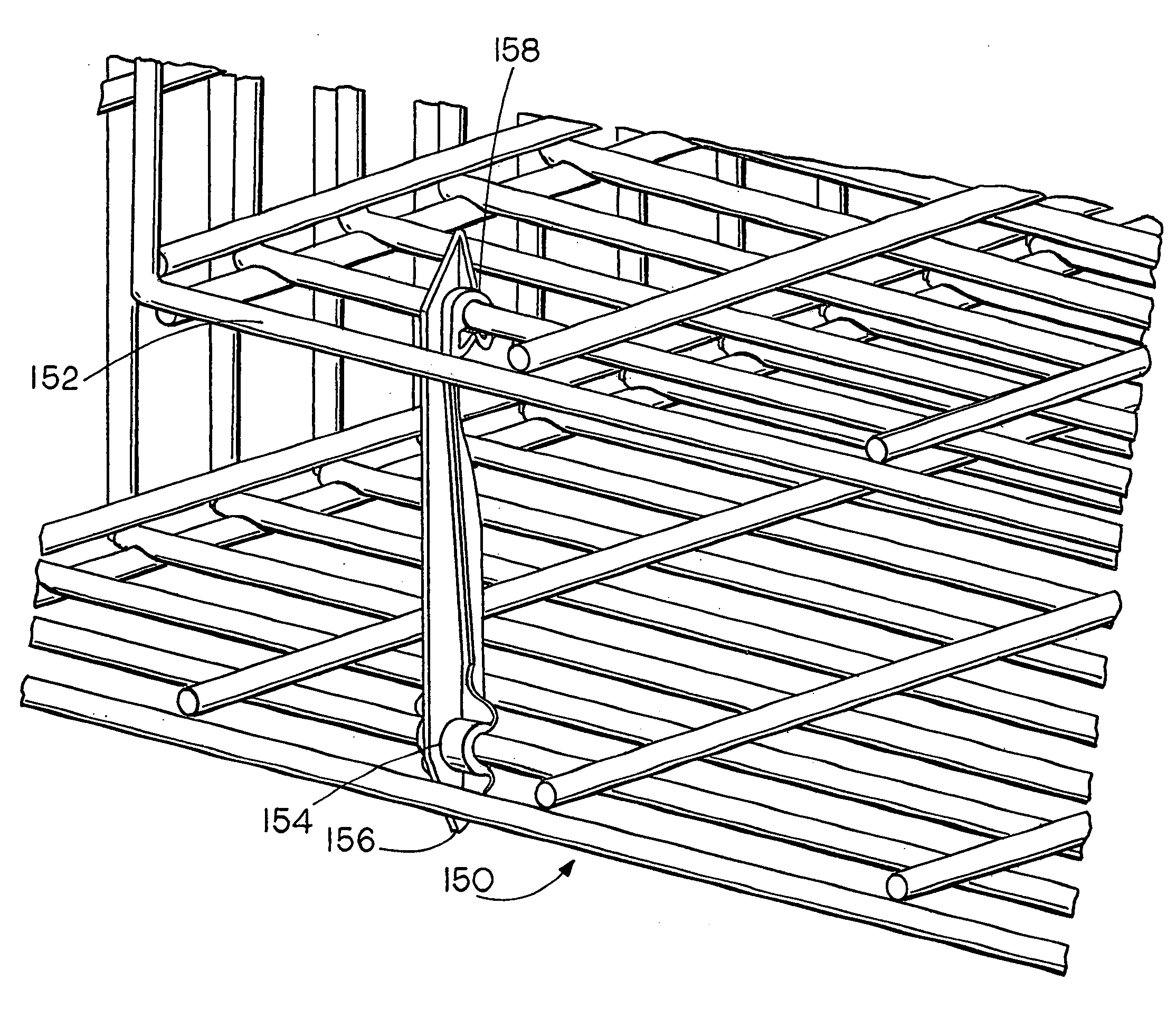
[0009]The present invention provides versatile spacer device designs for use wherever a plurality of reinforcing fabric shapes are employed in a concrete form. The spacers are easily installed even though very dense mesh weaves may be used and the devices lock into place with a minimum of manipulation. The spacers include a pair of spaced locking portions including first and second locking portions, each having a recess for receiving a fabric element and a trapping and retaining component for capturing and retaining a received fabric element. A generally straight central portion connects the pair of spaced locking portions and access to the pair of spaced locking portions is designed for positive attachment and ease of assembly.
[0010]The spacer is configured so that the first locking portion has an entrance directed generally such that the spacer can be inserted through an opening in the mesh of a first or near fabric and snapped onto an element of a second spaced fabric either by directly snapping onto the element or by hooking over the element and being retracted to lock the first portion onto the element of the second fabric. At this point, the second locking portion is configured such that it can be simply snapped directly onto a corresponding element of the first fabric. Thus, the first locking portion can have an entry directed away from the central portion or back toward the second locking portion but, in either case, assembly involves only a push-pull or linear motion and a finger grip may be provided on one end of the spacer element making assembly even easier.
[0011]A mold spacer extension can be provided on one or both ends of the spacer element depending on the particular application of the element. The distance between the locking portions and the size of the locking portions themselves can be varied such that spacers of different sizes can easily be fabricated. Spacers are preferably molded from relatively high-strength plastic materials, but metal components are also contemplated.
[0013]It will also be appreciated that the spacer of the present invention can be made as strong as desired by molding in a reinforcing rib or even using a metal core to increase the strength of the device. It will also be appreciated that the molded plastic spacers of the present invention will not corrode and deteriorate over time and will maintain their integrity.

Problems solved by technology

Pouring steps may be particularly stressful to the framework.
While these devices do space fabrics from each other and from mold walls, they require sections of wire or rods to be formed in intricate patterns that must be manipulated into place to attach to the mesh fabrics and that remains quite a labor-intensive assembly operation, even though welding or ties may not be necessary.

Method used


Image

  • Multi-cage spacer
  • Multi-cage spacer
  • Multi-cage spacer

Examples


Embodiment Construction

[0024]The following detailed description pertains to several embodiments of the inventive concept, each of which is presented by way of example rather than with any intent to limit the scope of the inventive concepts. It will be recognized that additional variations may occur to those skilled in the art which also would come within the scope of the inventive concept.

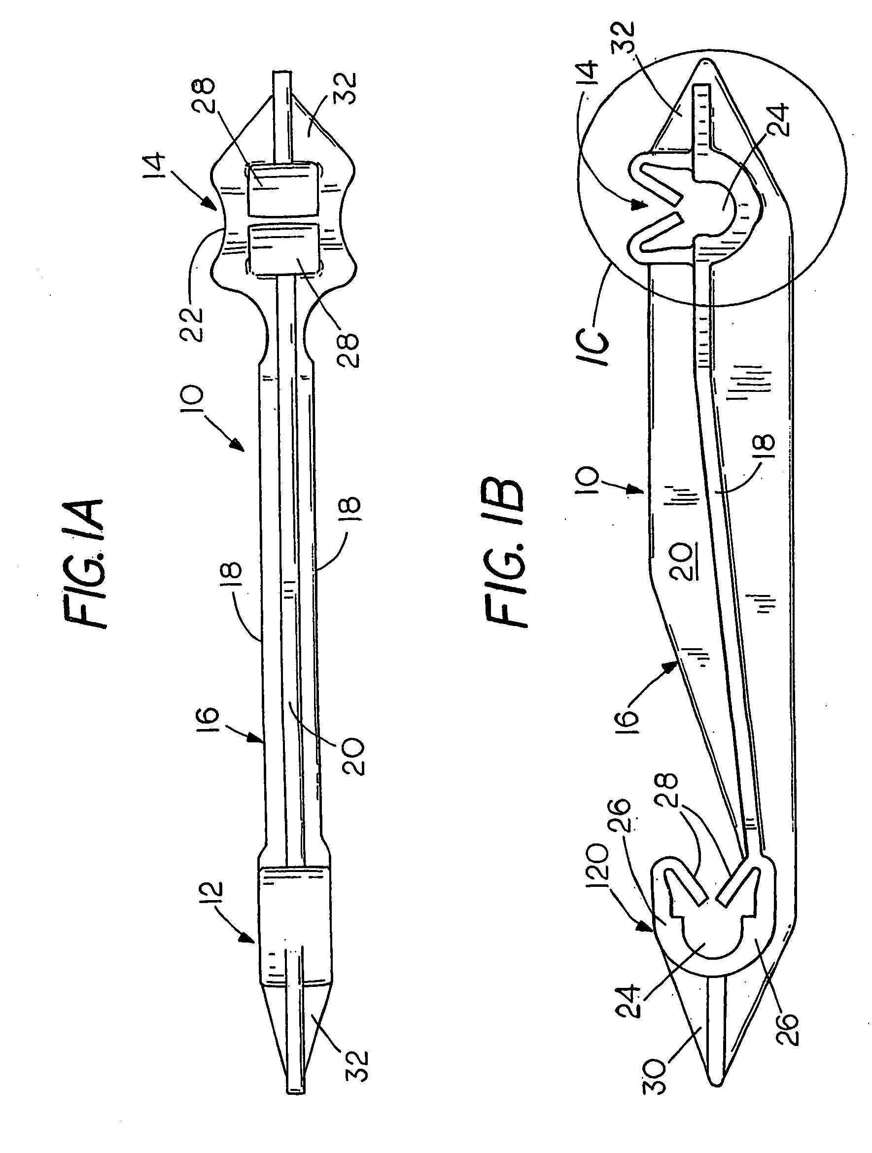
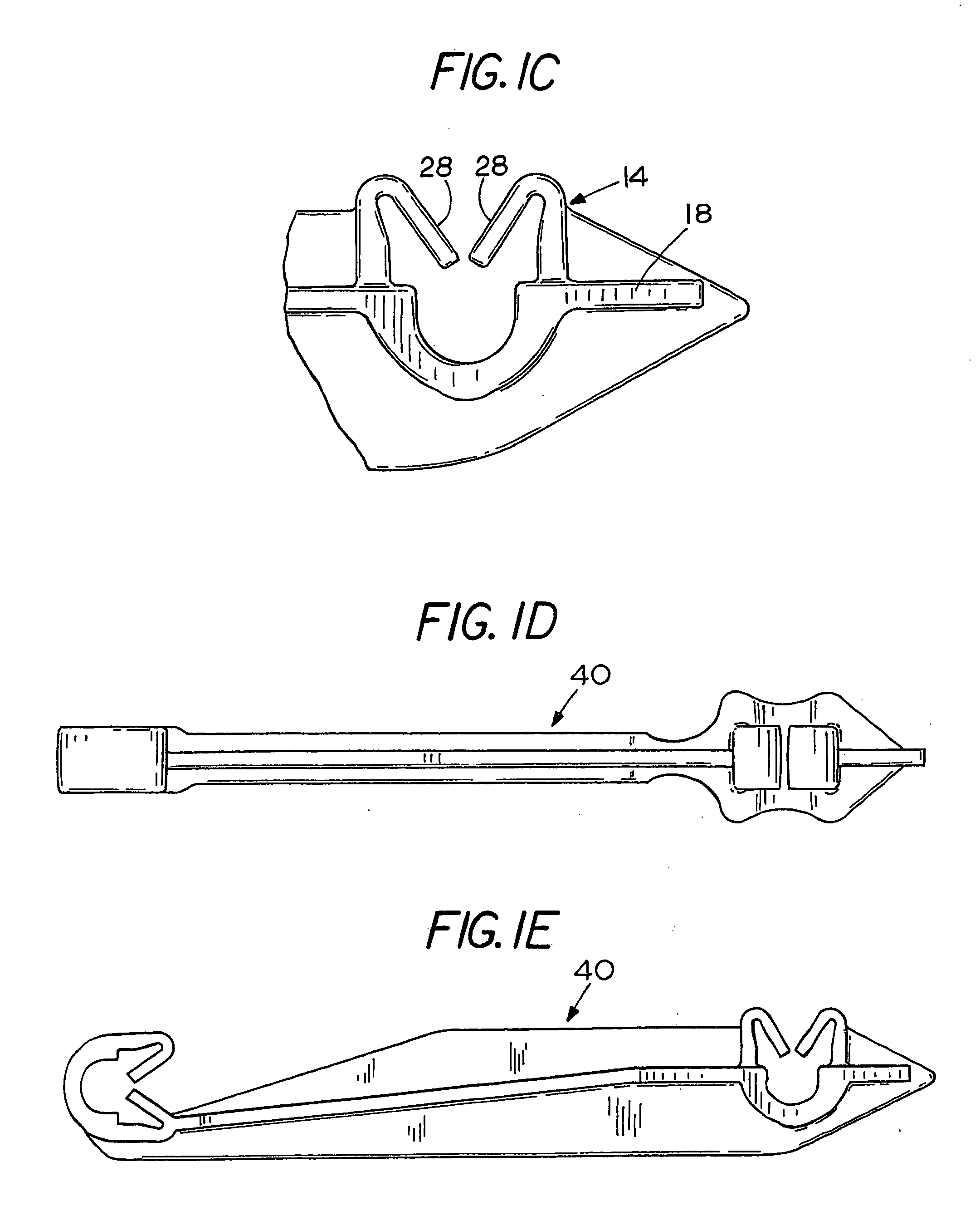
[0025]FIGS. 1A-1C illustrate a typical spacer element in accordance with the invention. The spacer element is depicted generally at 10 and includes first and second locking portions 12 and 14 spaced by a generally straight central portion 16. The structure includes a reinforcing rib 18 which runs the length of the structure 10 and is generally perpendicular to a central connecting fin 20. A finger grip is provided at the vicinity of the second locking portion as shown at 22. Each of the locking portions 12 and 14 includes a reinforcing fabric element receiving portion which might be a rebar engaging portion 24 with suppo...


PUM


Abstract

A spacer for positioning and locking spaced reinforcing cages into a combined integral unit for reinforcing large concrete structures is disclosed that is readily snapped into place even with narrow lattice cages.

Description

CROSS-REFERENCED TO RELATED APPLICATIONS[0001]Not applicableSTATEMENT REGARDING FEDERALLY SPONSORED RESEARCH OR DEVELOPMENT[0002]Not applicableBACKGROUND OF THE INVENTION[0003]I. Field of the Invention[0004]The present invention relates generally to spacer devices used in conjunction with reinforcement structures for large concrete articles such as pipes, boxes and building structures. More particularly, the concept as related to spacers for use in maintaining concentric or parallel reinforcing assemblies in spaced relation relative to each other and to a form or mold in the fabrication of concrete structures.[0005]II. Related Art[0006]The manufacture of reinforced concrete structures often involves the use of a pair of steel mesh fabric shapes disposed in spaced parallel relation within the structure and spaced from the surfaces of the structure. In boxes, tanks, pipes or other enclosed structures, may resemble concentric mesh fabric cages and may be round, square, rectangular or o...

Claims


Application Information

Patent Timeline
IPC IPC(8): E04C5/16E04B1/21
CPCE04C5/168E04C5/162
Inventor TRANGSRUD, JULIAN P.
Owner FORTERRA CONCRETE PROD INC
Learn More