Two-dimensional antenna configuration

a two-dimensional antenna and configuration technology, applied in the field of samples, can solve the problems of ice-impaired reading by humans or optical scanners, poor writing surface, and little room for extensive information

Active Publication Date: 2010-12-02
BIOTILLION
View PDF14 Cites 30 Cited by
  • Summary
  • Abstract
  • Description
  • Claims
  • Application Information

AI Technical Summary

Problems solved by technology

Problems are many, including: poor writing surfaces, little room for extensive information, ice-impaired reading by humans or optical scanners, difficulty locating a particular sample among up to 20,000 or more samples in a typical freezer, loss of records or memory containing information on arrangements of collections, personnel turnover, accidental mixing or spilling of collections, and the inevitable confusion when reorganizing collections for new projects.

Method used


Image

  • Two-dimensional antenna configuration
  • Two-dimensional antenna configuration
  • Two-dimensional antenna configuration

Examples


Embodiment Construction

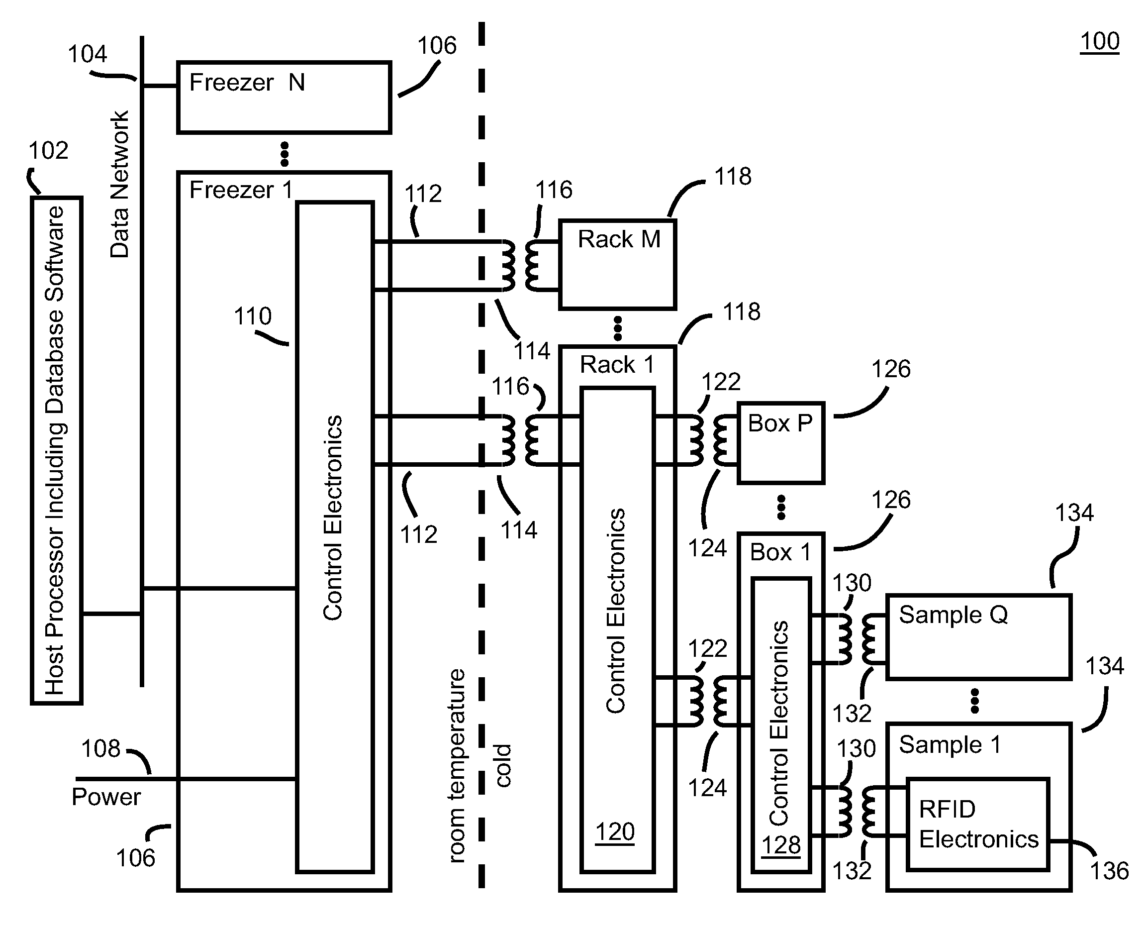
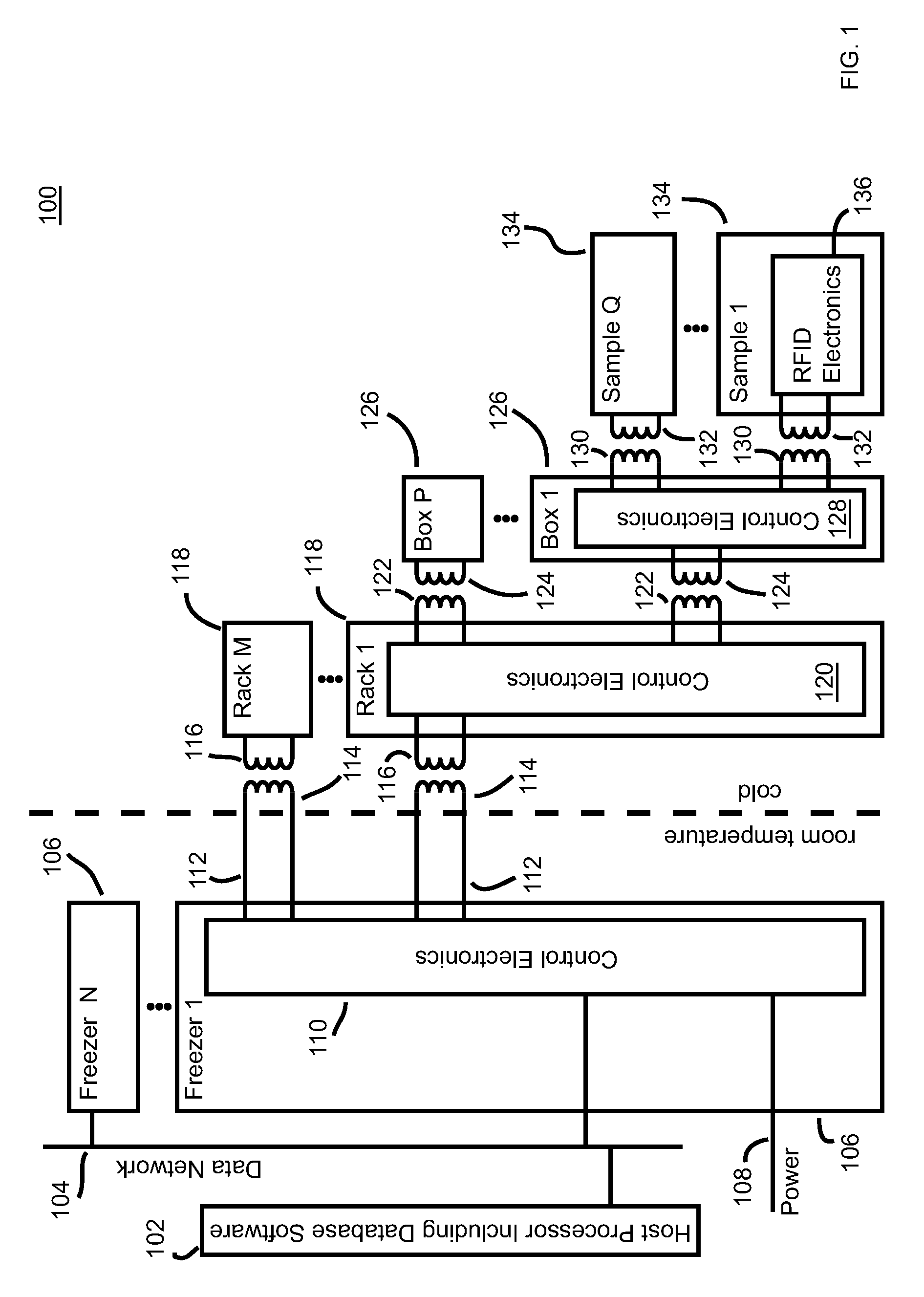
[0031]FIG. 1 shows a block diagram of cold storage system 100, according to one embodiment of the present invention. Cold storage system 100 includes (remote or local) host computer 102 in communication with one or more freezers 106 via a suitable, preferably secure data network 104 (e.g., based on a standard interface, such as, BlueTooth, USB 2.0, IEEE 802.3 (Ethernet), or a wireless technology, such as, but not limited to 802.11 in its various forms). Each freezer 106 has freezer control electronics 110 and one or more racks 118. Each rack 118 has rack control electronics 120 and can support one or more boxes 126. Each box 126, in turn, has box control electronics 128 and locations (i.e., slots) for receiving one or more sample containers 134, each of which has radio frequency identification (RFID) tag electronics 136 and a biological sample (not shown), where the RFID tag is physically separated from the biological sample. Biological samples may be of any type, including but not ...


PUM


Abstract

In one embodiment, an antenna configuration for locating RFID tags has two sets of (mutually orthogonal) elongated reader coils, where each elongated reader coil corresponds to two or more different possible locations of RFID tags, and each possible location is associated with one reader coil in each of the two sets. The identities and locations of RFID tags can be determined by (sequentially) energizing the different sets of reader coils and correlating the recorded responses from RFID tags. In one application, the antenna configuration is used at the box level of a cold storage system for biological samples having one or more freezers, each freezer having one or racks, each rack receiving one or more boxes, each box receiving one or more sample containers, where, in addition to the biological sample, each sample container has a unique passive RFID tag.

Description

CROSS-REFERENCE TO RELATED APPLICATIONS[0001]This application claims the benefit of the filing date of U.S. provisional application No. 61 / 181,454, filed on May 27, 2009, U.S. provisional application No. 61 / 220,318, filed on Jun. 25, 2009, and U.S. provisional application No. 61 / 304,481, filed on Feb. 14, 2010, the teachings of all of which are incorporated herein by reference.[0002]The subject matter of this application is related to U.S. patent application Ser. No. 12 / 064,748, filed on Feb. 25, 2008 as attorney docket no. 1136.001, the teachings of which are incorporated herein by reference.BACKGROUND OF THE INVENTION[0003]1. Field of the Invention[0004]The present invention relates to the storage of samples, such as the cold storage of biological samples in freezers.[0005]2. Description of the Related Art[0006]Biological samples are collected and stored in many different types of facilities, for a great variety of applications. Such applications include the storage of samples col...

Claims


Application Information

Patent Timeline
Patent Type & Authority Applications(United States)
IPC IPC(8): G08B13/14
CPCG08B13/2431G01S13/878
Inventor DAVIDOWITZ, HANANELCORADETTI, THOMASALTMAN, THEODOREKOVNATSKY, ILYA
Owner BIOTILLION
Why Eureka
Try Eureka