Touch panel and display apparatus having the same

Active Publication Date: 2010-12-02
TRIVALE TECH LLC
View PDF1 Cites 62 Cited by
  • Summary
  • Abstract
  • Description
  • Claims
  • Application Information

AI Technical Summary

Benefits of technology

[0015]An object of the present invention is to obtain a touch panel with improved

Problems solved by technology

On the other hand, since a touch panel is mainly used with a display apparatus, the visibility of the conductive material patterns can be a problem as a display characteristic.
However, such touch panels are likely to suffer reduced sensing accuracy because the transparent conductive film forming the sensing lines generally has high resistance value.
Accordingly, it was difficult to upsize touch panels in which the sensing lines are made of a transparent conductive film.
However, when the sensing lines are formed of plain lines, the large areas of the lines degrad

Method used


Image

  • Touch panel and display apparatus having the same
  • Touch panel and display apparatus having the same
  • Touch panel and display apparatus having the same

Examples


Example

[0024]First, the structure of a touch screen 1 of a touch panel 100 according to a preferred embodiment of the present invention will be described.

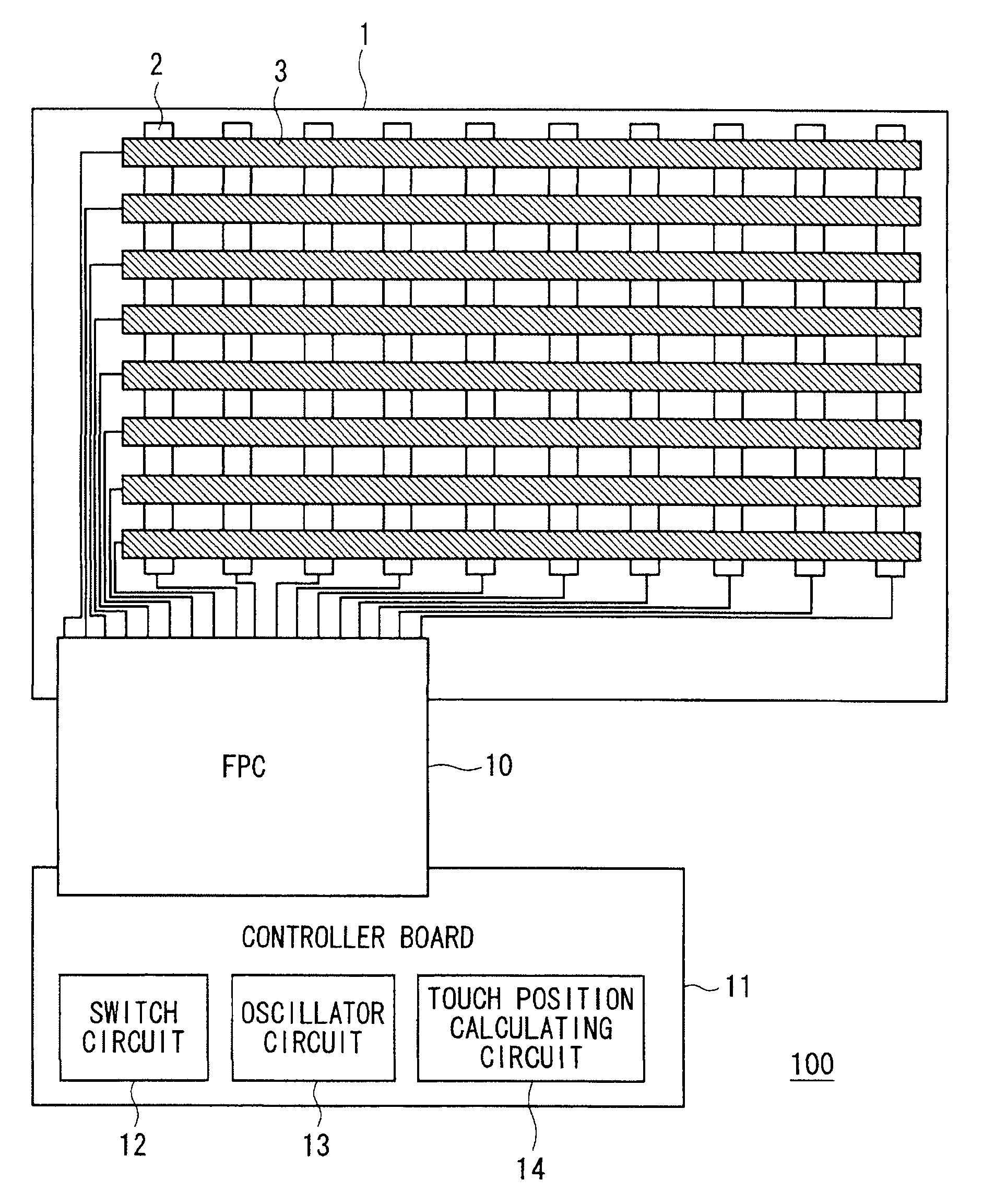
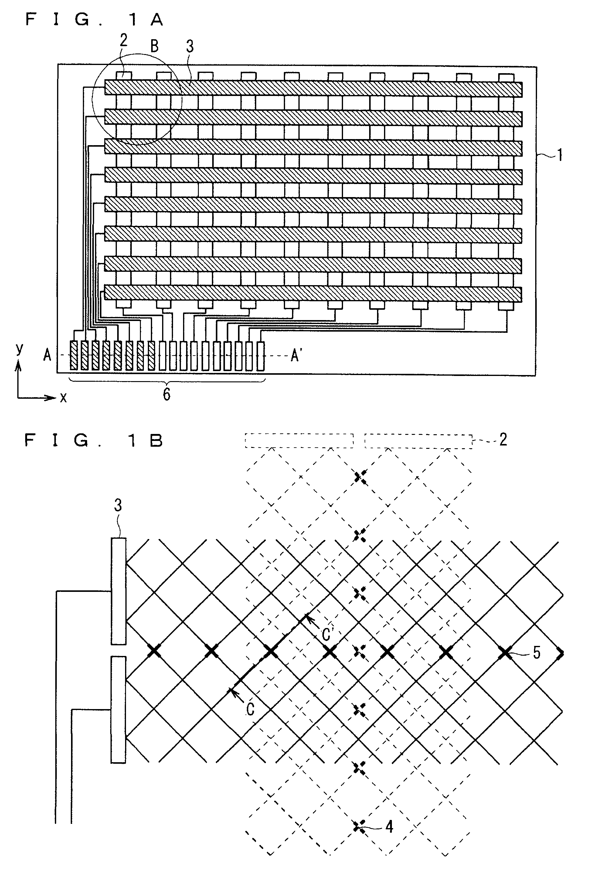
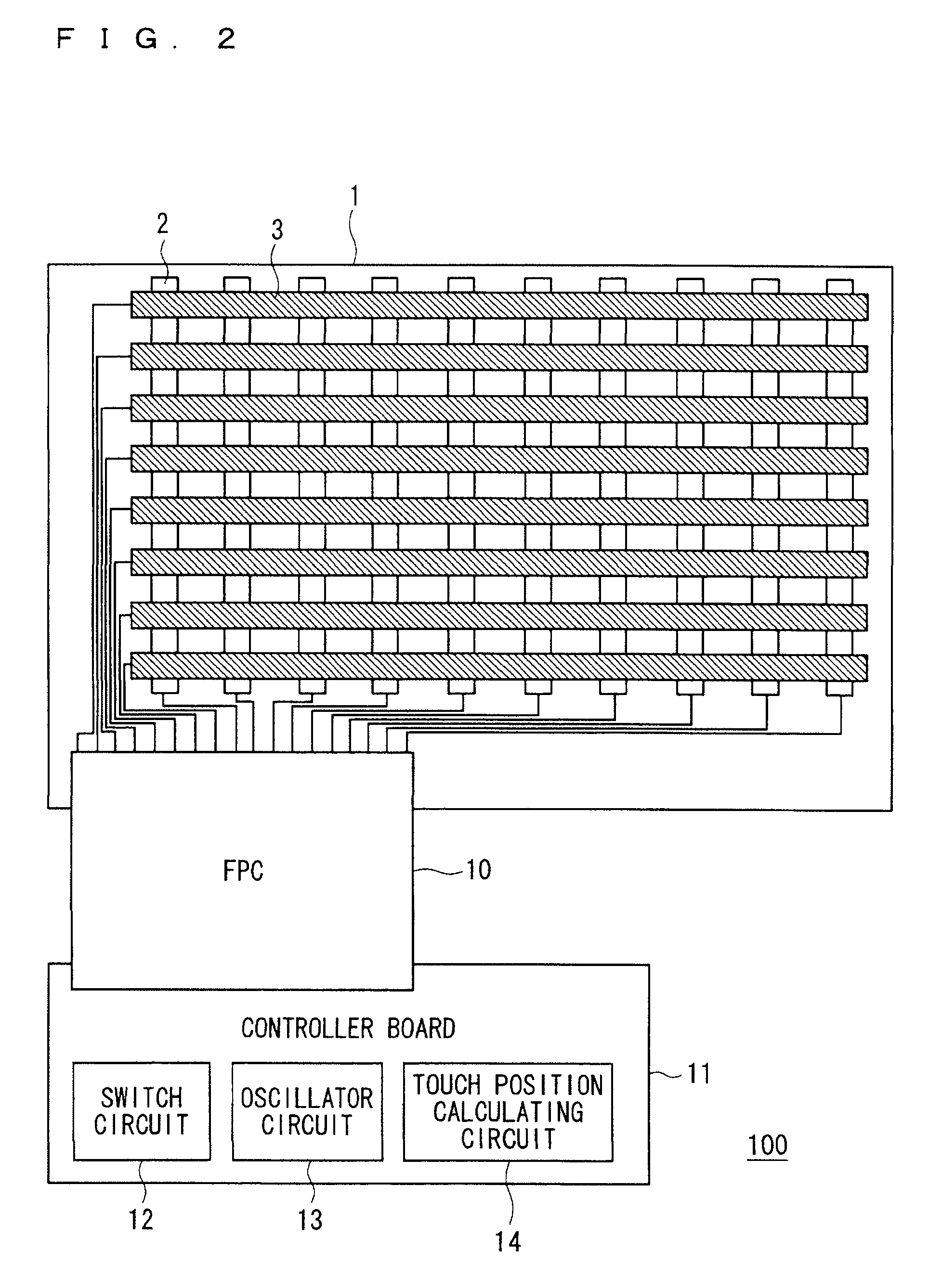
[0025]FIG. 1A is a plan view schematically illustrating the structure of the touch screen 1 of the preferred embodiment of the present invention. FIG. 1B is a diagram illustrating the region B in FIG. 1A in an enlarged manner. The touch screen 1 includes a plurality of sensing column lines 2 extending in the column direction (in y direction in FIG. 1A) and arranged in parallel at given intervals in the row direction (in x direction in FIG. 1A), a plurality of sensing row lines 3 extending in the row direction and arranged in parallel at given intervals in the column direction, and a plurality of terminals 6 for electrically connecting the sensing lines and external parts. As shown in FIG. 1B, the sensing column lines 2 and the sensing row lines 3 are formed of regularly arranged mesh-like conductors.

[0026]The touch screen 1 further includ...


PUM


Abstract

An object is to obtain a touch panel with improved sensitivity and enhanced display quality. A touch panel according to the present invention includes a touch screen including a plurality of first sensing lines formed of mesh-like conductors and arranged in parallel on a substrate, an insulating film formed over the substrate and the first sensing lines, a plurality of second sensing lines formed of mesh-like conductors and arranged in parallel on the insulating film, first dummy patterns arranged in areas opposed to areas between adjacent first sensing lines through the insulating film, and having a form as part of the mesh forms of the first sensing lines such that the adjacent first sensing lines form an apparently continuous mesh form in plan view, and second dummy patterns arranged in areas opposed to areas between adjacent second sensing lines through the insulating film, and having a form as part of the mesh forms of the second sensing lines such that the adjacent second sensing lines form an apparently continuous mesh form in plan view.

Description

BACKGROUND OF THE INVENTION[0001]1. Field of the Invention[0002]The present invention relates to a touch panel and a display apparatus having the touch panel.[0003]2. Description of the Background Art[0004]The touch panel function is conventionally known and receiving attention as one of good interface means, where a touch by, e.g. a finger, on the touch panel is detected and the coordinates of the touched position are specified for input operation. Such touch panels are manufactured as products using various schemes for detecting the position of touch by, e.g. a finger, such as resistive film schemes and capacitive schemes, for example.[0005]The PCT (Projected Capacitive Touch screen) scheme is known as one of the capacitive schemes, where the front side of a touch screen having a touch sensor is covered by a protective plate, e.g. a glass plate having a thickness of several millimeters, such that a touch by, e.g. a finger on the protective plate can be detected (for example, refer...

Claims


Application Information

Patent Timeline
IPC IPC(8): G06F3/045
CPCG06F3/0418G06F3/044G06F2203/04112G06F3/0445G06F3/0446
Inventor MIYAYAMA, TAKASHIMORI, SEIICHIRO
Owner TRIVALE TECH LLC
Why Eureka
Try Eureka