
Inter-domain coordination for mt and mo calls

a technology of inter-domain coordination and mt and mo, applied in the field of inter-domain coordination, can solve problems such as the inability to set up the call

Active Publication Date: 2010-12-02
TELEFON AB LM ERICSSON (PUBL)
View PDF3 Cites 85 Cited by
  • Summary
  • Abstract
  • Description
  • Claims
  • Application Information

AI Technical Summary

Benefits of technology

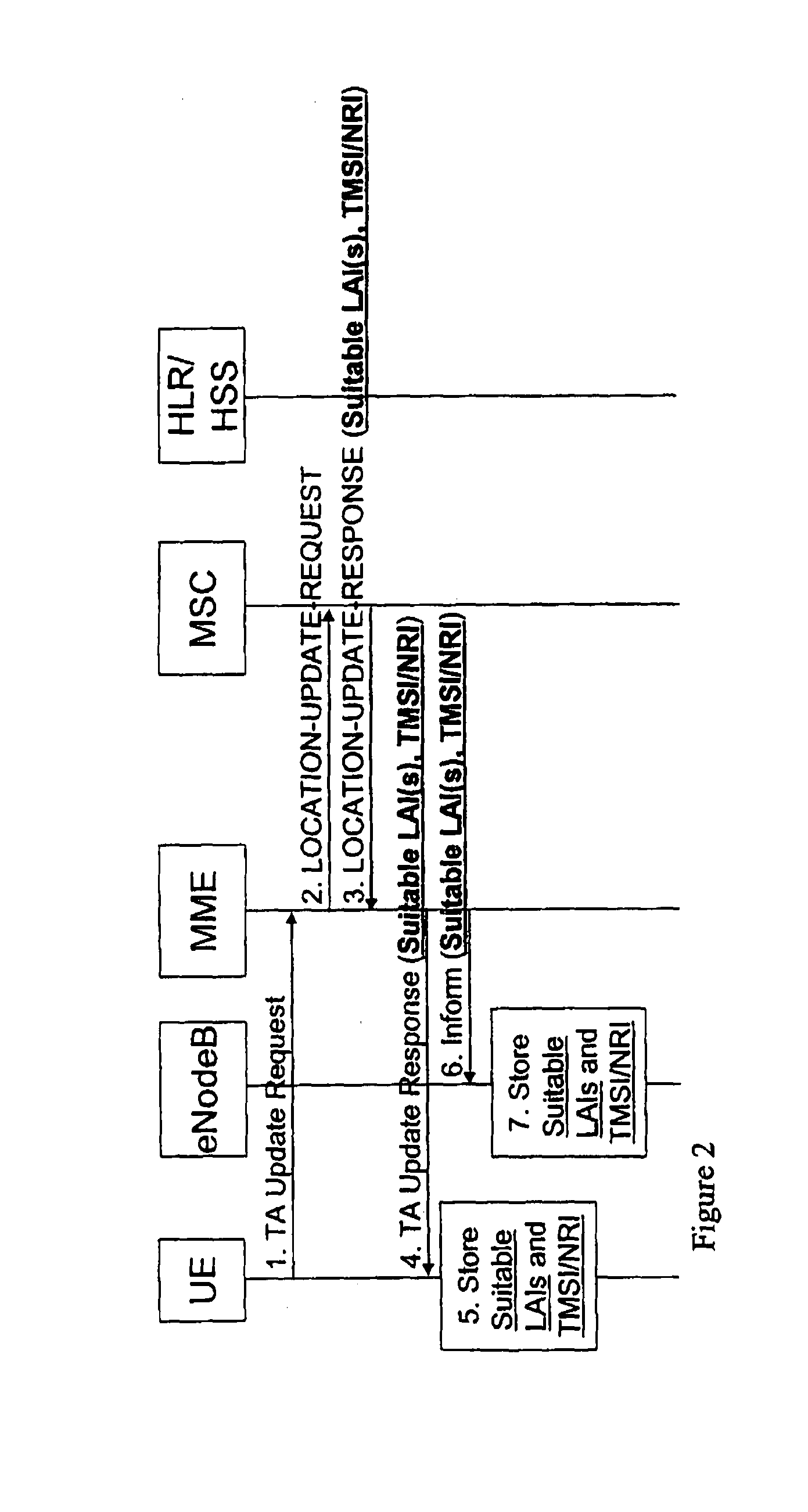
[0004]The present invention pertains to a mobility management entity (MME) for setting up a call. The MME comprises a first network interface which receives a tracking area update (TAU) request from a user equipment (UE). The MME comprises a processing unit which translates the TAU request into a location area update (LAU) request. The MME comprises a second network interface in communication with the processing unit which sends the LAU request to a mobile switching center (MSC) selected as a tracking MSC thereby establishin...

Problems solved by technology

The lack of IMS support for call establishment means that whenever a call (i.e. speech) needs to be established the UE must stop being served by the LTE network and start being served by a GSM or UMTS network for the purpose of performing the control plane signaling required for establishing the call.
In other words, unless a transition from the LTE network to a GSM or UMTS network occurs when the need for call establishment is first detected, it will not be possible to set up the call.

Method used


Image

  • Inter-domain coordination for mt and mo calls
  • Inter-domain coordination for mt and mo calls
  • Inter-domain coordination for mt and mo calls

Examples


Embodiment Construction

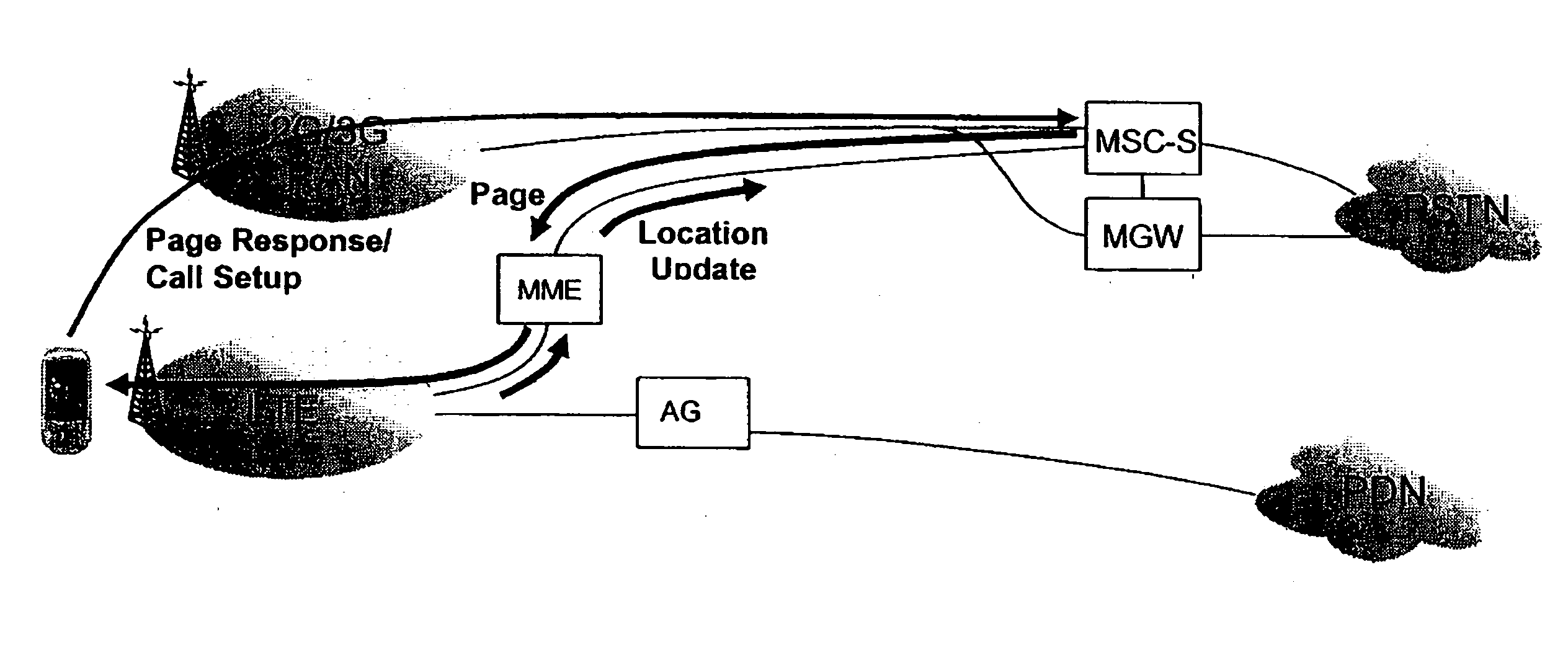
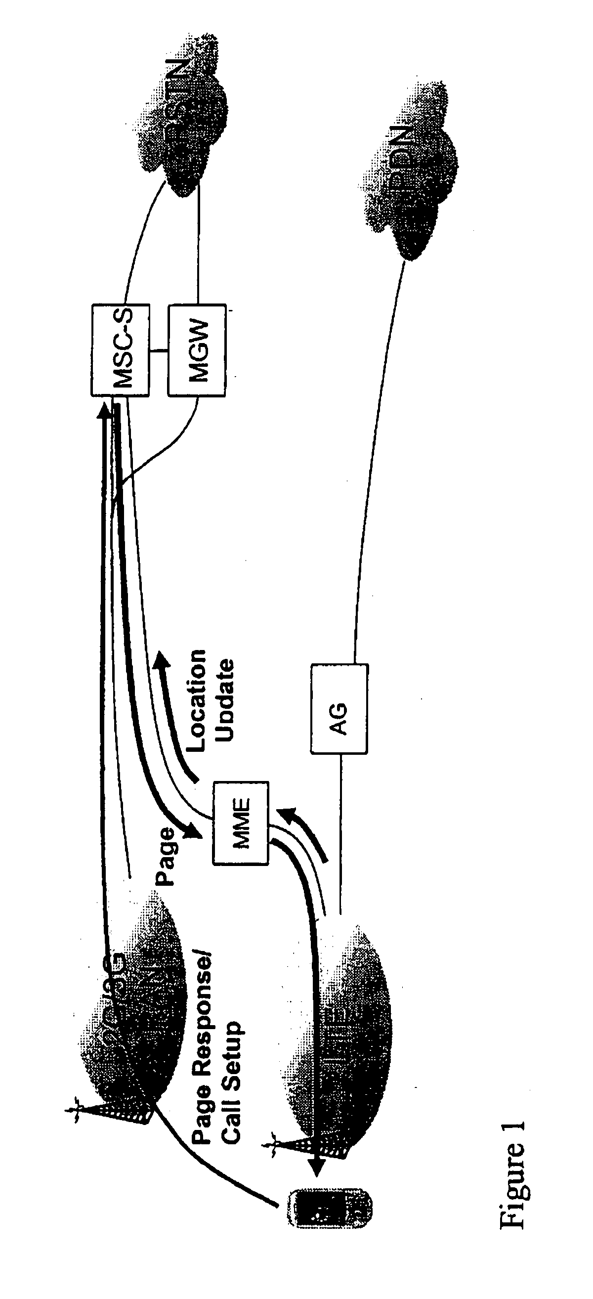
[0015]Referring now to the drawings wherein like reference numerals refer to similar or identical parts throughout the several views, and more specifically to FIGS. 1 and 5 thereof, there is shown a mobility management entity (MME) for setting up a call. The MME comprises a first network interface 12 which receives a tracking area update (TAU) request from a user equipment (UE). The MME comprises a processing unit 18 which translates the TAU request into a location area update (LAU) request. The MME comprises a second network interface 14 in communication with the processing unit 18 which sends the LAU request to a mobile switching center (MSC) selected as a tracking MSC thereby establishing the MME as a network node through which the UE is paged. The second network interface 14 receiving a LAU response from the tracking MSC that comprises at least information identifying one or more suitable location area identifiers (LAI(s)) to which handover is allowed and Network Resource Identi...


PUM


Abstract

A mobility management entity (MME) for setting up a call includes a first network interface which receives a tracking area update (TAU) request from a user equipment (UE). The MME includes a processing unit which translates the TAU request into a location area update (LAU) request. The MME includes a second network interface in communication with the processing unit which sends the LAU request to a mobile switching center (MSC) selected as a tracking MSC thereby establishing the MME as a network node through which the UE is paged. The second network interface receiving a LAU response from the tracking MSC that includes at least information identifying one or more suitable location area identifiers (LAI(s)) to which handover is allowed and Network Resource Identifier (NRI) information where the information indicates that the tracking MSC controls the suitable LAI(s), and the processing unit translating the LAU response into a TAU response which is sent through the first network interface to the UE. A user equipment (UE) includes a processing unit which transmits a tracking area update (TAU) request. The UE includes a network interface in communication with the processing unit which sends the TAU request to a mobility management entity (MME), and receives a TAU response having suitable location area identifiers (LAIs) and TMSI / network resource identifier (NRI). The UE includes a memory in communication with the network interface which stores the suitable LAIs and TMSI / NRI. A method for a mobility management entity (MME) for setting up a call. A method for a user equipment (UE).

Description

TECHNICAL FIELD[0001]The present invention is related to the transition of wireless user equipment (UE) from an LTE network to a GSM or UMTS network when a need for call establishment is first detected. (As used herein, references to the “present invention” or “invention” relate to exemplary embodiments and not necessarily to every embodiment encompassed by the appended claims.) More specifically, the present invention is related to the transition of a UE from an LTE network to a GSM or UMTS network when a need for call establishment is first detected for a UE operating in a given LTE cell either in idle mode or with one or more ongoing packet data services (all non speech) where the LTE network or the UE does not support the IP Multi-media Subsystem control plane functionality for call establishment.BACKGROUND[0002]This section is intended to introduce the reader to various aspects of the art that may be related to various aspects of the present invention. The following discussion ...

Claims


Application Information

Patent Timeline
IPC IPC(8): H04W36/16
CPCH04W36/14H04W60/04H04W68/12H04W92/02H04W36/1443
Inventor DIACHINA, JOHNVIKBERG, JARIOSTRUP, PETER
Owner TELEFON AB LM ERICSSON (PUBL)
Learn More